Thermal expansion valve

A thermal expansion valve and displacement technology, which is applied in the field of thermal expansion valves, can solve problems such as not considering resin materials, achieve the effects of suppressing thermal influence, avoiding plastic deformation, and prolonging service life

Active Publication Date: 2011-11-23
ZHEJIANG SANHUA AUTOMOTIVE COMPONENTS CO LTD
View PDF5 Cites 7 Cited by
  • Summary
  • Abstract
  • Description
  • Claims
  • Application Information

AI Technical Summary

Problems solved by technology

[0009] However, in the existing thermal expansion valve, the material of the diaphragm displacement limiting member as its constituent parts has not taken into account the use of resin materials that can suppress the influence of thermal deformation, and the use of the diaphragm that is not easily deformed plastically under the influence of pressure. Structure of Displacement Limiting Parts

Method used


Image

  • Thermal expansion valve
  • Thermal expansion valve
  • Thermal expansion valve

Examples


Embodiment Construction

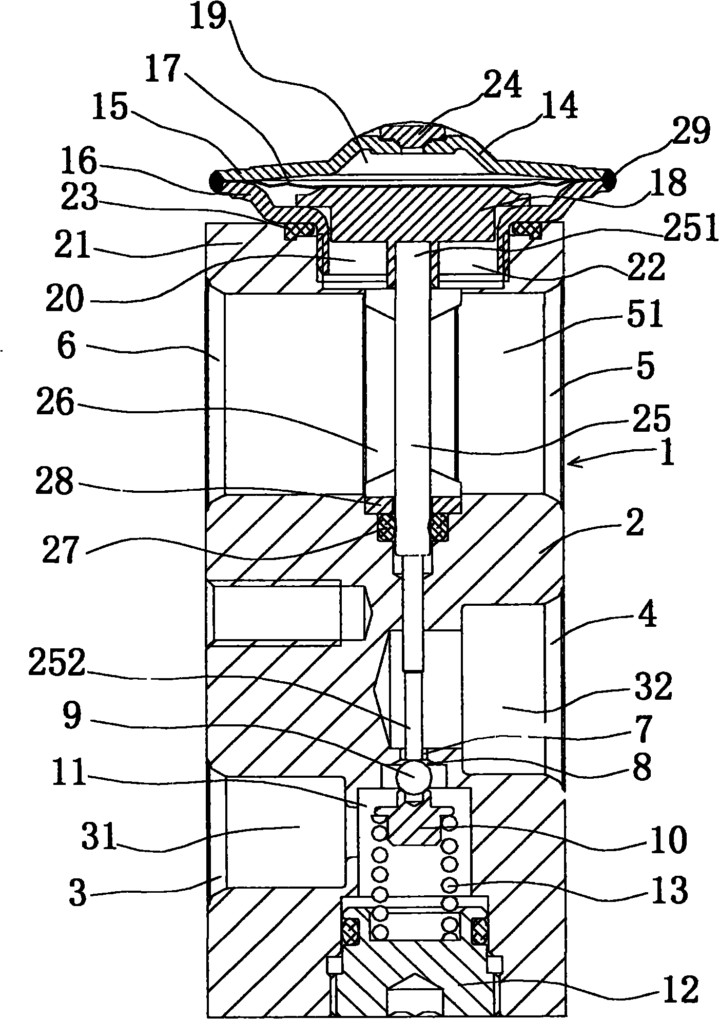
[0035] figure 1 It is a central longitudinal sectional structural view of the thermal expansion valve according to the first embodiment of the present invention.

[0036] In the thermal expansion valve 1 in the figure, connection holes 3, 4, 5 and 6 are formed on the side of the aluminum block valve body 2, wherein the connection holes 3 are connected with the high-temperature and high-pressure refrigerant from the liquid receiver for the inflow of refrigerant The connecting pipe is connected; the connecting pipe connecting hole 4 is connected to the refrigerant connecting pipe that introduces the low-temperature and low-pressure refrigerant that has been insulated and expanded by the thermal expansion valve into the evaporator; the connecting pipe connecting hole 5 is connected to the refrigerant connecting pipe at the outlet of the evaporator; and the connecting pipe The connection hole 6 is connected with the refrigerant connecting pipe that sends the refrigerant into the c...


PUM


Abstract

The invention discloses a thermal expansion valve. The thermal expansion valve is provided with a diaphragm, a diaphragm displacement limitation part and a transmission rod, wherein the diaphragm is displaced according to the temperature and pressure change of a low pressure coolant delivered by an evaporator; the diaphragm is arranged on the surface side of the diaphragm displacement limitation part; the transmission rod is arranged at the side opposite to the surface side of the diaphragm displacement limitation part and is used for transmitting the displacement; a high-pressure coolant flow rate of the evaporator is controlled through contact and separation between the transmission rod and a throttling hole of a valve core; the diaphragm displacement limitation part is made of polyphenylene sulfide; and the diaphragm displacement limitation part is integrated with a cylinder part arranged on the central part of the opposite side; and the upper end part of the transmission rod is inserted into the cylinder part, and the lower end part of the transmission rod is butted against the valve core. The thermal expansion valve can restrain thermal deformation and is not influenced by plastic deformation. Furthermore, the valve opening degree of the thermal expansion valve is rightly controlled; and the service life of the thermal expansion valve is prolonged.

Description

technical field [0001] The present invention relates to a thermal expansion valve, in particular to a refrigeration cycle used in the assembly of automobile air conditioners, which is used to expand the high-temperature and high-pressure refrigerant sent by the liquid receiver into a low-temperature and low-pressure refrigerant, and to control the supply of the low-temperature and low-pressure refrigerant to the evaporation valve. The flow rate of the thermostatic expansion valve. Background technique [0002] The thermal expansion valve includes an air box head installed on the valve body and a valve core arranged in the valve body. The air box head can sense the temperature and pressure of the outlet refrigerant sent by the evaporator. The temperature and pressure of the refrigerant to control the flow of refrigerant supplied to the evaporator. [0003] The specific process of the above control is as follows: the diaphragm of the gas tank head is displaced according to th...

Claims


Application Information

Patent Timeline
Patent Type & Authority Applications(China)
IPC IPC(8): F25B41/06
Inventor 裘浩明尹斌
Owner ZHEJIANG SANHUA AUTOMOTIVE COMPONENTS CO LTD
Why Eureka
Try Eureka