Dedicated photoelectric encoder with special insulation structure for wind driven generator

A technology for wind turbines and photoelectric encoders, applied in the field of photoelectric encoders, can solve the problems of reduced insulation performance, loss, difficulty in adapting insulation bearings, etc., and achieves the effect of increasing the breakdown voltage value, broadening the selection range, and freeing installation and debugging.

Inactive Publication Date: 2011-11-23
深圳市英科达光电技术有限公司
View PDF3 Cites 5 Cited by
  • Summary
  • Abstract
  • Description
  • Claims
  • Application Information

AI Technical Summary

Problems solved by technology

[0002] Most of the photoelectric encoders for wind turbines on the market use insulating bearings to prevent the wind turbine shaft current from being transmitted to the main body of the encoder, but insulating bearings are expensive, and their insulation performance is reduced or even lost under extreme temperatures to prevent breakdown The shaft voltage value is relatively low
With the increasing power of wind turbines, the insulation requirements for encoders are getting higher and higher, and the original insulating bearings are becoming more and more difficult to adapt to
Others use the method of encoder insulation adapter shaft to achieve the purpose of insulation. The installation of encoder insulation adapter shaft is very complicated, and it is necessary to add insulation connectors, increase the axial length, and the cost is high.

Method used


Image

  • Dedicated photoelectric encoder with special insulation structure for wind driven generator
  • Dedicated photoelectric encoder with special insulation structure for wind driven generator
  • Dedicated photoelectric encoder with special insulation structure for wind driven generator

Examples


Embodiment Construction

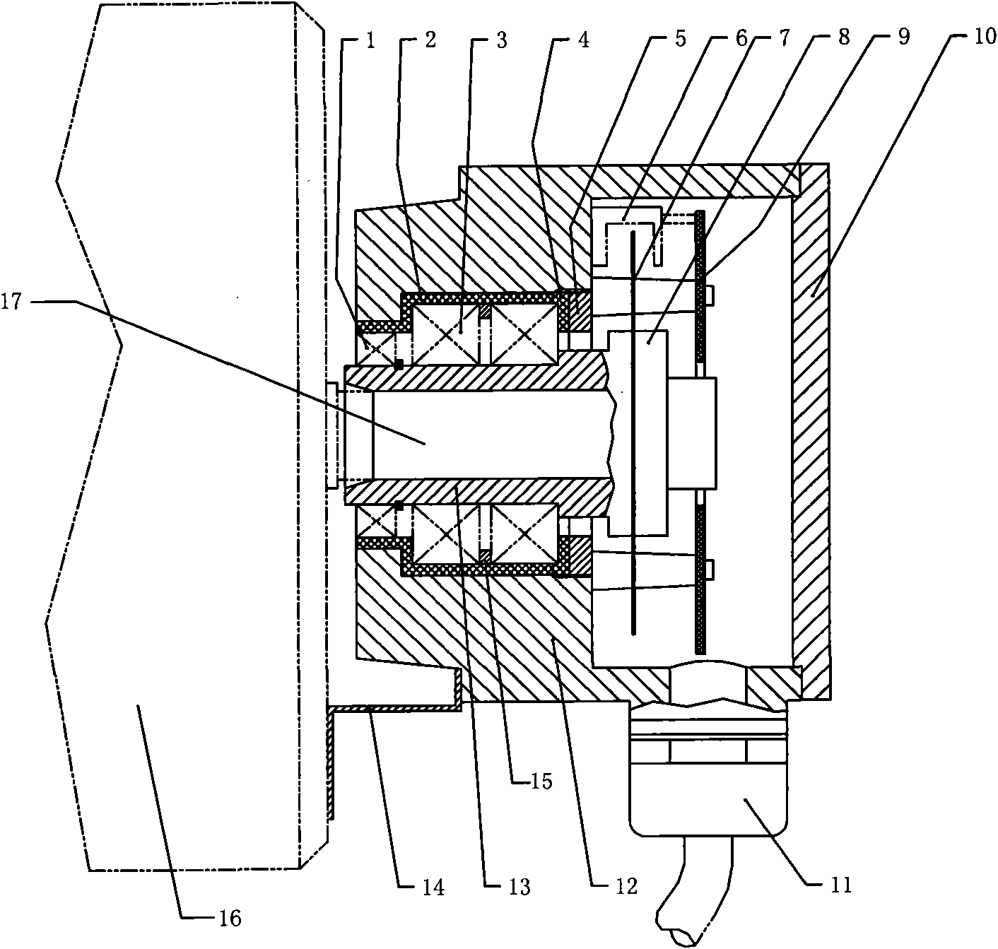
[0033] A special photoelectric encoder for wind power generators with a special insulating structure, including a seal 1, an insulating sleeve 2, a bearing 3, an insulating gland 4, a threaded pressing part 5, a photoelectric system 6, a grating disc 7, a support ring 8, and a circuit Plate 9, rear cover 10, waterproof cable connector 11, encoder main body 12, hollow shaft 13, fixing bracket 14, spacer ring 15. The hollow shaft 13 is fixedly connected with the output shaft 17 of the generator according to the precision matching requirements, and the grating disc 7 is fixed on the hollow shaft 13 by the support ring 8; 1. The threaded pressing part 5 is connected to the encoder main body 12; a spacer ring 15 is arranged between the double bearings; a photoelectric system 6 (including a light-emitting tube corresponding to the code track of the grating disk, an indicating grating and an array of photoelectric receiving elements), a circuit board 9 is installed on the main body o...


PUM


Abstract

The invention discloses a dedicated photoelectric encoder with a special insulation structure for a wind driven generator, comprising a sealing element, an insulating sleeve, bearings, an insulating gland, a threaded compression element, a photoelectric system, a grating disk, a support ring, a circuit board, a rear cover, a waterproof cable connector, a coder main body, a hollow shaft, a fixed support and a space ring, wherein the hollow shaft is fixedly connected with an output of the generator in accordance with the accuracy matching requirement; the grating disk is fixed on the hollow shaft by the support ring; the hollow shaft is connected with the coder main body by the sealing element, the two bearings, the insulating sleeve, the insulating gland and the threaded compression element; the space ring is arranged between the two bearings; the photoelectric system and the circuit board are arranged on the coder main body; the coder main body is fixed on the generator frame by the fixed support; and cables are connected with the circuit board and are output by the waterproof sealed cable connector. The dedicated photoelectric encoder is simple in structure, low in cost and good in insulation performance, can improve the breakdown voltage value greatly, and meets the high-reliability and long-life working requirements in heavy-load and severe environments; and by using the dedicated photoelectric encoder, insulation bearings can not be used.

Description

technical field [0001] The invention relates to a photoelectric encoder, in particular to a photoelectric encoder for a wind power generator with a special insulating structure. Background technique [0002] Most of the photoelectric encoders for wind turbines on the market use insulating bearings to prevent the wind turbine shaft current from being transmitted to the main body of the encoder, but insulating bearings are expensive, and their insulation performance is reduced or even lost under extreme temperatures to prevent breakdown The shaft voltage value is relatively low. With the increasing power of wind turbines, the insulation requirements for encoders are getting higher and higher, and the original insulating bearings are becoming more and more difficult to adapt. Others use the method of encoder insulation adapter shaft to achieve the purpose of insulation. The installation of encoder insulation adapter shaft is very complicated. Additional insulation connectors a...

Claims


Application Information

Patent Timeline
Patent Type & Authority Applications(China)
IPC IPC(8): H02K11/00H02K11/22
Inventor 熊文凯卢动熊文硕
Owner 深圳市英科达光电技术有限公司
Why Eureka
Try Eureka