In hoistway sheave resurfacing

A sheave and coating technology, applied in the field of elevator systems, can solve the problems of increasing the size and cost of the elevator system

Inactive Publication Date: 2011-11-23
OTIS ELEVATOR CO
View PDF10 Cites 6 Cited by
  • Summary
  • Abstract
  • Description
  • Claims
  • Application Information

AI Technical Summary

Problems solved by technology

[0006] If larger sheaves are used for longer life or to accommodate additional rope or thicker sections of steel rope

Method used


Image

  • In hoistway sheave resurfacing
  • In hoistway sheave resurfacing
  • In hoistway sheave resurfacing

Examples


Embodiment Construction

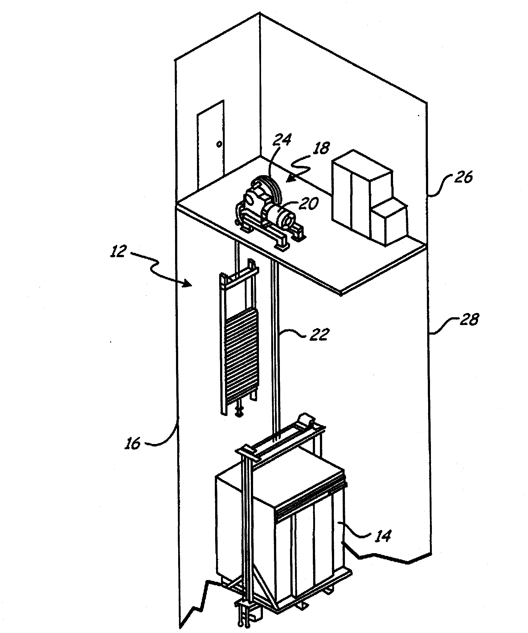
[0013] like figure 1 As shown, the traction elevator system 12 includes a car 14 , a counterweight 16 , a traction drive 18 , and a machine or motor drive unit 20 . The traction drive 18 includes a tension member 22 interconnecting the car 14 and the counterweight 16 , and a traction sheave 24 . The system shown is a 1:1 rope system. The present invention is not dependent on a particular rope system, but functions to repair sheaves in any rope system such as a 2:1 rope system and any other elevator system in which sheaves and ropes or other tension members are used surface.

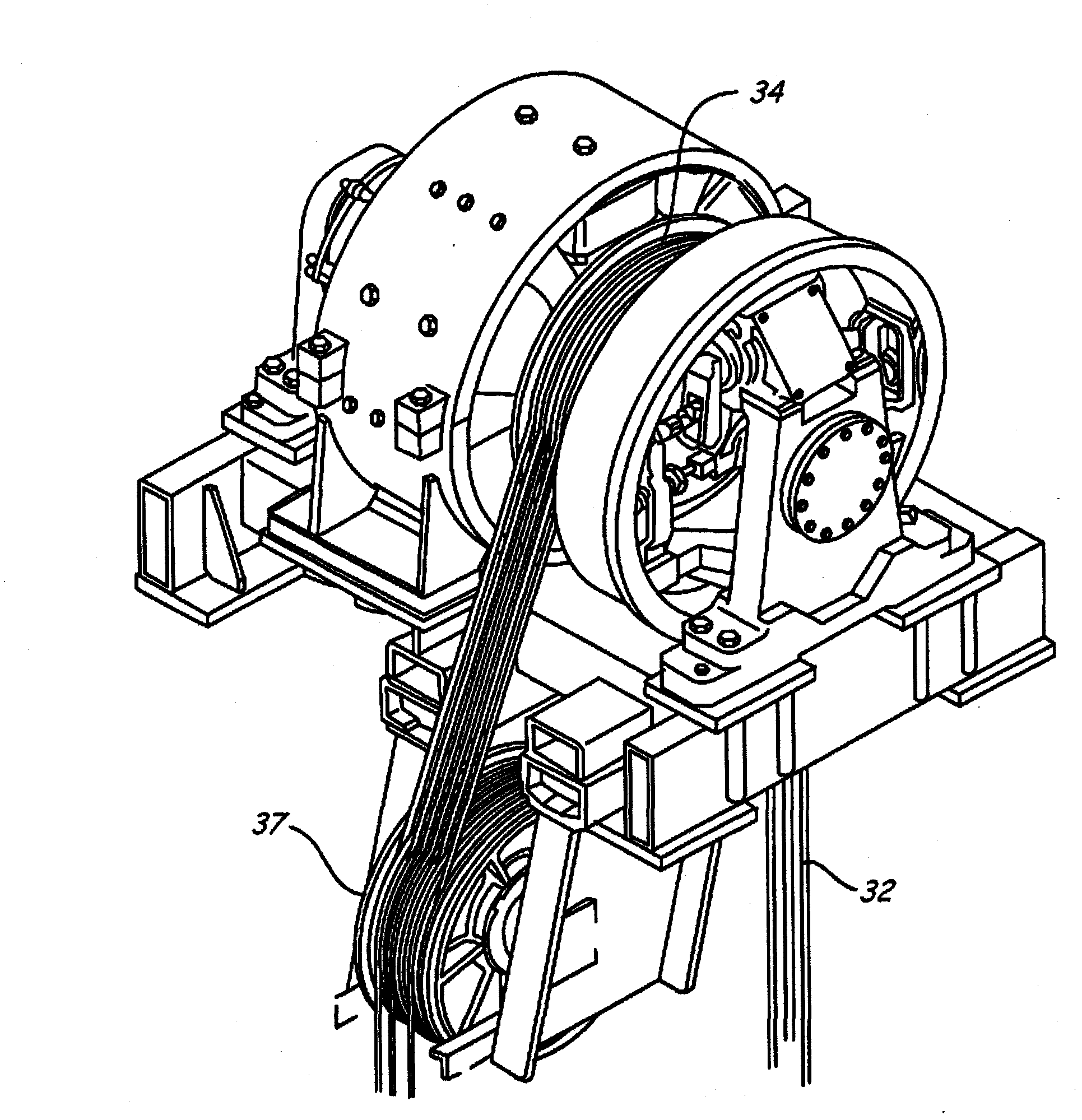
[0014] In order to achieve a desired rope arrangement in the elevator hoistway, the elevator system may comprise one or more deflector sheaves. The rope engages the deflector sheave, but unlike the traction sheave, it does not drive the rope. image 3 Deflector sheave 37 is shown acting to divert the path of tension member 32 driven by drive sheave 34 .

[0015] Lift systems can also include safety s...


PUM

PropertyMeasurementUnit
Thicknessaaaaaaaaaa
Wear factoraaaaaaaaaa

Abstract

A method of and system for repairing the sheaves (24) in an elevator system has these steps. The ropes (22) associated with the sheave are removed, the sheave is cleaned, and a coating (24) is deposited on the cleaned surface. The coating is adapted to reduce the wear coefficient of the surface of the coated sheave by about 80 % to 90 % with respect to the sheave without a coating. The thickness of the coated sheave is adjusted to produce a specified sheave diameter.

Description

Background technique [0001] The present invention relates to elevator systems, and more particularly, to elevator sheaves that are subject to wear during use. [0002] A conventional traction elevator system typically includes a car, a counterweight, two or more tension members (such as round ropes) interconnecting the car and counterweight, a traction sheave to move the rope, and a A machine to rotate the traction sheave. The machine may be either a geared or gearless machine. Geared machines allow the use of higher speed motors, which are more compact and less costly, but require additional maintenance and space. [0003] The rope (whether the rope is for the car and counterweight or for the overspeed governor) may be formed from laid or twisted steel wire, while the sheave (whether drive sheave, deflector sheave or governor sheave sheaves) may be formed from cast iron. Differential tension on the sides of the sheave, or deformation of the rope caused by the applied tens...

Claims


Application Information

Patent Timeline
IPC IPC(8): B66B15/04F16H55/50
CPCB66B15/04F16H55/50F16H57/041B66B11/08
Inventor J·T·比尔斯M·S·汤普森W·R·施米德特A·T·纳迪G·S·维尔什
Owner OTIS ELEVATOR CO
Why Eureka
Try Eureka