Fuel injector drive system

A fuel injection device and drive system technology, which is applied in the field of drive systems and fuel injection device drive systems, can solve the problems of reducing fuel injection quality and inaccurate positioning, and achieve the goals of ensuring accuracy, enhancing adaptability, and overcoming uncertainty Effect

Inactive Publication Date: 2011-11-30
SIP GOLDWAY TECH
View PDF5 Cites 2 Cited by
  • Summary
  • Abstract
  • Description
  • Claims
  • Application Information

AI Technical Summary

Problems solved by technology

[0003] The above-mentioned automatic rotary fuel injection device drives the fuel injection device to reciprocate in the axial direction of the rotating shaft through the driving system of the fuel injection device, and then realizes all the oil spraying on the surface of the rotating shaft, while the traditional driving system is in the process of driving , when the piston shakes, the fuel injection needle of the fuel injection device driven by it will also be inaccurately positioned on the upper surface of the rotating shaft, which will reduce the fuel injection quality

Method used


Image

  • Fuel injector drive system
  • Fuel injector drive system

Examples


specific Embodiment approach

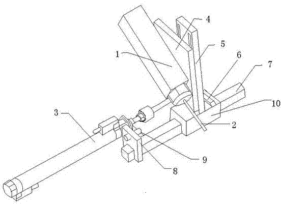
[0016] figure 1 It is a structural schematic diagram of an embodiment of the present invention.

[0017] Such as figure 1 As shown: the rotary fuel injection device includes a fuel injection needle 2, an oil supply device 1 for supplying oil to the fuel injection needle 2, a rotating shaft seat that forms the oil injection space of the rotating shaft, and can drive the fuel injecting needle 2 along the axial direction of the rotating shaft The driving system of the fuel injection device that performs reciprocating motion on the shaft seat, wherein the shaft seat is provided with a shaft and a cavity of the shaft driving device, the shaft driving device is fixed in the shaft driving device cavity on the shaft seat, and the shaft is suspended on the shaft In the rotating shaft cavity of the seat, the cross section of the rotating shaft cavity is a U-shaped long groove, and the rotating shaft is horizontally arranged in the U-shaped long groove, and it does not contact with the ...


PUM


Abstract

The invention discloses a driving system of a fuel injection device, which comprises a driving cylinder and a connecting plate, wherein the top end of the piston of the driving cylinder is fixedly connected with the connecting plate, and the fuel spraying device is fixed on the connecting plate, and is characterized in that, The drive system of the fuel injection device also includes a slide block and a guide rail, the guide rail is fixed on the operating platform, it is arranged parallel to the piston, and the slide block is arranged at the bottom end of the connecting plate, and the slide block is provided with a Grooves for a slip fit. The present invention effectively ensures the accuracy of positioning, effectively overcomes the uncertainty of the position of the oil outlet of the fuel injection needle, and ensures the quality of the product. The relative sliding fit realizes the up and down movement of the fuel injection device and enhances the adaptability of the fuel injection device to different products and fuel injection requirements.

Description

technical field [0001] The invention relates to a driving system, in particular to a driving system of a fuel injection device used for rotary shaft rotation and fuel injection, and belongs to the technical field of fuel injection equipment. Background technique [0002] We know that a layer of nearly solid oil needs to be coated on the rotating shaft used for driving to lubricate, and the oil spraying treatment on the surface of the rotating shaft, if you want to spray evenly, you need to spray oil on the rotating shaft At present, the rotary oil injection device used usually includes an oil injection needle, an oil supply device for supplying oil to the oil injection needle, a rotating shaft seat that forms the oil injection space of the rotating shaft, and a shaft that can drive the oil injecting needle along the rotating shaft. The driving system of the fuel injection device that reciprocates in the axial direction, wherein the rotating shaft seat is provided with a rota...

Claims


Application Information

Patent Timeline
Patent Type & Authority Applications(China)
IPC IPC(8): B05B15/10B05B13/04
Inventor 沈皓然
Owner SIP GOLDWAY TECH
Why Eureka
Try Eureka