Processing method of slender shaft

A processing method and technology for slender shafts, which are applied in the field of machining, can solve the problems of easy vibration of slender shafts, high rejection rate, and knife sticking, and achieve the effects of reducing rejection rate, improving runout detection, and satisfying runout detection.

Active Publication Date: 2011-11-30
QINGDAO YUANDING THERMAL & ENVIRONMENTAL ENG CO LTD
View PDF6 Cites 9 Cited by
  • Summary
  • Abstract
  • Description
  • Claims
  • Application Information

AI Technical Summary

Problems solved by technology

The surface roughness Ra of the slender shaft is required to be in the range of 0.1~0.8. Since the length of the slender shaft is larger than the diameter, the slender shaft is easy to vibrate

Method used


Image

  • Processing method of slender shaft
  • Processing method of slender shaft

Examples


Embodiment Construction

[0026] In order to make the purpose, technical solutions and advantages of the embodiments of the present invention clearer, the technical solutions in the embodiments of the present invention will be clearly and completely described below in conjunction with the drawings in the embodiments of the present invention. Obviously, the described embodiments It is a part of embodiments of the present invention, but not all embodiments. Based on the embodiments of the present invention, all other embodiments obtained by persons of ordinary skill in the art without creative efforts fall within the protection scope of the present invention.

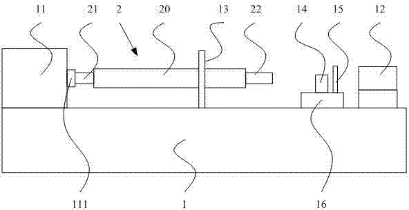
[0027] figure 1 It is a schematic structural diagram of the equipment used in the embodiment of the slender shaft processing method of the present invention. Such as figure 1 As shown, the slender shaft processing method of the present embodiment includes:

[0028] Step 1. Alignment of the workpiece 2 to be processed: the first end 21 of the wo...


PUM


Abstract

The invention provides a processing method of a slender axle. The method comprises the following steps: step 1, aligning workpiece to be processed; step 2, processing a second end of the workpiece to be processed; step 3, fashioning the second end of the workpiece to be processed; step 4, processing middle part of the workpiece to be processed; step 5, turning around the workpiece to be processed; step 6, processing a first end of the workpiece to be processed; step 7, fashioning the first end of the workpiece to be processed; and step 8, polishing the whole body. Through processing the two ends of the workpiece to be processed step by step, the slender axle, which better meets requirements of surface roughness, beating test, static balance test and dynamic balance test, can be preferablyproduced. Because beating test for the workpiece to be processed is implemented twice during processing period, breaking edge phenomenon of the workpiece to be processed is reduced due to vibration and rejection rate of processing the slender axle is also decreased.

Description

technical field [0001] The invention relates to the field of machining, in particular to a machining method for a slender shaft. Background technique [0002] Currently, slender shafts with a length-to-diameter ratio greater than 25 are widely used in industrial production. The surface roughness Ra of the slender shaft is required to be in the range of 0.1~0.8. Since the length of the slender shaft is larger than the diameter, the slender shaft is easy to vibrate during the process of finishing the surface of the slender shaft. Knives appear, resulting in a higher reject rate. Therefore, the rejection rate of processing the elongated shaft in the prior art is relatively high. Contents of the invention [0003] The technical problem to be solved by the present invention is to provide a processing method for slender shafts, which solves the defect of high reject rate in processing slender shafts in the prior art, and realizes reducing the reject rate of processing slender ...

Claims


Application Information

Patent Timeline
IPC IPC(8): B23B1/00
Inventor 孙东升卜范德李垒
Owner QINGDAO YUANDING THERMAL & ENVIRONMENTAL ENG CO LTD
Why Eureka
Try Eureka