Multi-block one-time forming mold with convenient mold assembly and disassembly

A molding mold, a convenient technology, applied in the direction of molds, mold separation devices, etc., can solve the problems of heavy metal door panels, deformation of joint parts, etc., and achieve the effects of good product integrity, less failure, and improved labor efficiency

Active Publication Date: 2011-11-30
NINGBO PINGHAI BUILDING MATERIALS
View PDF6 Cites 17 Cited by
  • Summary
  • Abstract
  • Description
  • Claims
  • Application Information

AI Technical Summary

Problems solved by technology

But there are also some defects: the front and rear door panels are arranged on the fixed plate or the movable partition, and the partition groove is also provided on the door panel to coincide with the side of the movable partition when the mold is clo

Method used


Image

  • Multi-block one-time forming mold with convenient mold assembly and disassembly
  • Multi-block one-time forming mold with convenient mold assembly and disassembly
  • Multi-block one-time forming mold with convenient mold assembly and disassembly

Examples


Embodiment 1

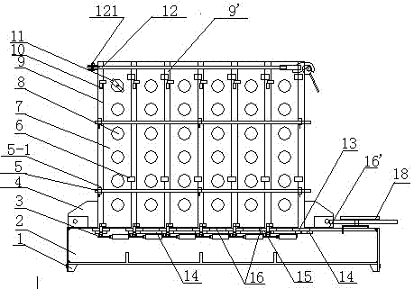
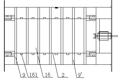
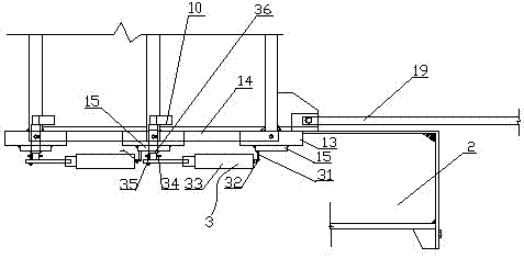
[0044] Such as Figure 1-9 As shown, the multi-block one-time molding mold with convenient assembly and disassembly includes: a base frame 2, a fixing plate 9 arranged on the left side (or right side) of the base frame and vertically fixed on the base frame, six pieces and The fixed plates are equal in size and parallel to each other with movable vertical partitions 9', the front and rear door panels 7 which are perpendicular to the fixed panels 9 or the movable vertical partitions 9' and are parallel to each other, and the front and rear door panels 7 which are arranged on the A plurality of core holes 8 corresponding to each other are inserted into the plugging tube 17 in the core hole 8; it is characterized in that: between the fixed plate 9 and the movable vertical partition 9' and two adjacent movable vertical partitions Rectangular flat plate 16 is set on the said underframe 2 between the plates 9'; front and rear door panels 7 are arranged on the sides of said fixed pla...

Embodiment 2

[0058] Example 2 is roughly the same as Example 1. The difference is that "the round platform cap 11 screwed into the core hole 3 replaces the plugging tube 17 inserted in the core hole 3. The round platform cap 11 is mainly composed of a round platform 111, a long baffle plate 112 and a fixing screw 113. Screw Move fixed screw 113, make the round flat part of round platform 111 withstand the inner wall of core hole 8 places on front and rear door panels 7, and long baffle plate 112 withstand the outer wall of core holes 8 places on front and rear door panels 7. In this way, The round platform of the round platform cap 11 has been fixed on the front and rear door panels 7. After the block forming and division, there is no through hole on the block, but there is also a round platform small hole that is convenient for swinging the block. If the round platform cap 11 round platform 111 If the part is designed to be flat and smaller, the round table hole on the side of the formed ...


PUM


Abstract

The invention discloses a conveniently assembled and disassembled mould for once molding multiple building blocks. The mould comprises a base frame, fixed plates, movable vertical clapboards, front door plates, back door plates, a plurality of mutually corresponding core holes, and hole blocking pipes, wherein the fixed plates are arranged on the left or right side of the base frame and are vertically fixed on the base frame, the movable vertical clapboards are as same as the fixed plates and are parallel to the fixed plates one another, the front door plates and the back door plates are vertical and mutually parallel to the fixed plates or the movable vertical clapboards, the plurality of mutually corresponding core holes are arranged on the front door plates and the back door plates, and the hole blocking pipes are inserted into the core holes. Rectangular flat plates are arranged between the fixed plates and the movable vertical clapboards or two adjacent movable vertical clapboards and on the base frame. The front door plates and the back door plates are arranged on sides of the fixed plates and the movable vertical clapboards, the two side bottoms of the fixed plates and themovable vertical clapboards are fixedly connected with reinforcing base plates, the reinforcing base plates can slide on the side of the upper end of the base frame, and the lower edges of the reinforcing base plates are fixedly connected with connecting plates. Front-back door plate automatic opening and closing mechanisms are arranged between the connecting plates and door hinges of the lower parts of the adjacent front, back door plates. A vertical clapboard pulling mechanism is arranged between two adjacent connecting plates. The mould disclosed by the invention is convenient to assemble,disassemble and maintain and is not easy to have fault.

Description

technical field [0001] The invention relates to an appliance for processing and manufacturing building materials-blocks, in particular to a multi-block one-time forming mold which is convenient for assembly and disassembly. Background technique [0002] At present, the used blocks of building walls are formed piece by piece with molds, and several pieces are formed at the same time. The production efficiency of forming one piece is too low; most of the molds are very complicated for the production of several pieces formed at the same time. Also have a kind of at present and be made into a large-scale building block by a large-scale mold earlier, then cut into required building blocks with cutting machine vertical several knives and horizontal several knives again by specification requirement. It is relatively simple to make its mold in this way, but a lot of raw materials will be wasted in the cutting process, and what is more serious is: the noise generated during cutting ...

Claims


Application Information

Patent Timeline
IPC IPC(8): B28B7/22B28B7/16B28B7/26
Inventor 朱籽臻
Owner NINGBO PINGHAI BUILDING MATERIALS
Why Eureka
Try Eureka