A kind of solar module lamination machine and lamination method thereof
A technology for solar modules and laminators, applied in the directions of lamination, lamination devices, chemical instruments and methods, etc., can solve the problems of poor bonding performance and air bubbles in solar cell modules, and achieve the effect of improving bonding performance and wide application.
- Summary
- Abstract
- Description
- Claims
- Application Information
AI Technical Summary
Problems solved by technology
Method used
Image

Examples
Embodiment Construction
[0039] The object of the present invention is to provide a lamination method of a solar module laminator and improve accordingly Solar module laminator to achieve this lamination method.
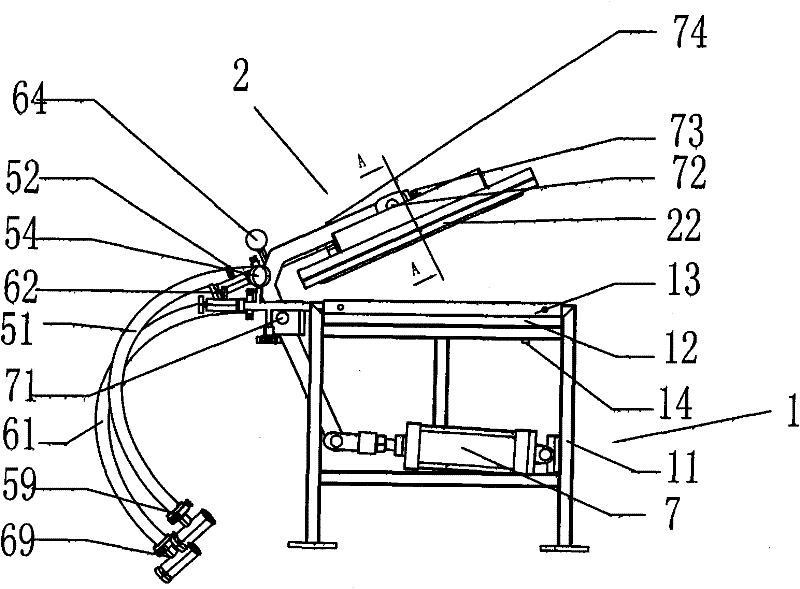
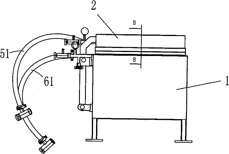
[0040] Such as figure 1 and figure 2 As shown, the solar laminator of the present invention includes: a laminator body 1 and an upper cover 2 , and the upper cover 2 is mounted on the body 1 in an openable manner. Specifically, the body 1 is provided with a double-cylinder actuator 7, the double-cylinder actuator 7 is connected with the upper cover 2 through a piston pin 71 and a piston pin 72, and the double-cylinder actuator 7 controls the upper cover 2. The cover 2 is opened or closed relative to the body 1 .
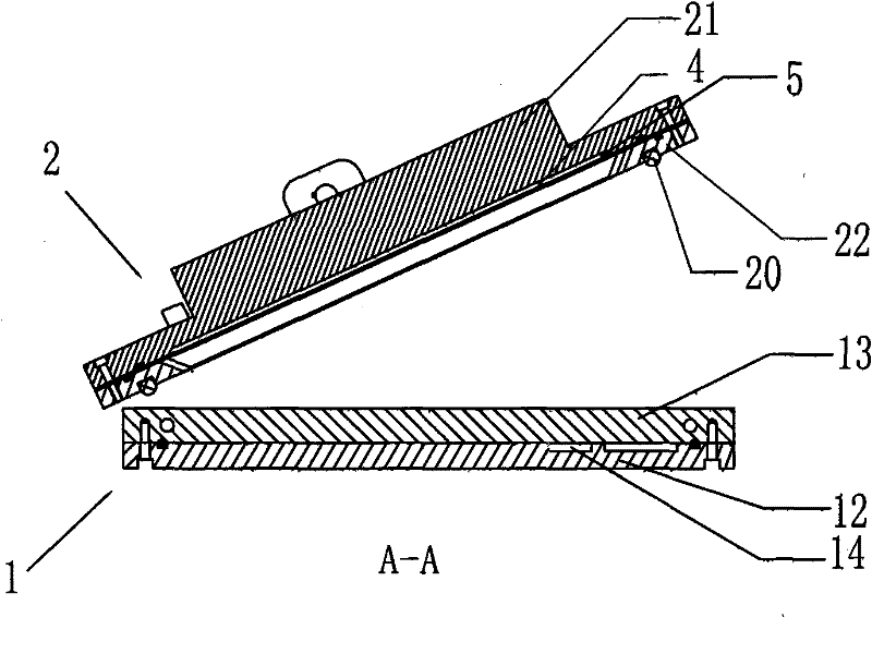
[0041] refer to Figure 4, the upper cover 2 and the body 1 are sealed to form a lower chamber 6 for accommodating solar cell components; the upper cover 2 is provided with a solar laminate 4 for laminating solar cell components, and the solar laminate 4 and the upper An uppe...
PUM
| Property | Measurement | Unit |
|---|---|---|
| Thickness | aaaaa | aaaaa |
Abstract
Description
Claims
Application Information
 - Generate Ideas
- Intellectual Property
- Life Sciences
- Materials
- Tech Scout
- Unparalleled Data Quality
- Higher Quality Content
- 60% Fewer Hallucinations
Browse by: Latest US Patents, China's latest patents, Technical Efficacy Thesaurus, Application Domain, Technology Topic, Popular Technical Reports.
© 2025 PatSnap. All rights reserved.Legal|Privacy policy|Modern Slavery Act Transparency Statement|Sitemap|About US| Contact US: help@patsnap.com