A feeding tray of an automatic feeding device

An automatic material feeding and tray technology, applied in the direction of vibrating conveyors, conveyors, conveyor objects, etc., can solve the problems of uneven concentricity, increased cost, loose shafts, etc., to achieve reduced production costs, reasonable structural design, The effect of reducing manual operations

Inactive Publication Date: 2011-11-30
GUANGDONG GALANZ GRP CO LTD
View PDF6 Cites 12 Cited by
  • Summary
  • Abstract
  • Description
  • Claims
  • Application Information

AI Technical Summary

Problems solved by technology

The traditional operation method is to manually insert the shaft into the synchronous motor housing by hand, and use a press to rivet the shaft. This requires a lot of workers to work semi-manually. This operation method greatly increases the cost of labor and cannot guarantee The quality of the shaft inserted into the timer housing often has problems such as loose shafts and uneven concentricity. To solve the problems, people hope to develop an automatic shaft riveting machine, which can carry out automated production, reduce labor costs and improve product quality; When developing the automatic riveting machine, it was difficult to arrange the housings of the synchronous motors, and it was still necessary to manually sort and determine the direction; for this reason, it is urgent to invent an automatic feeding device that can adjust the speed, automatically sort and determine the direction

Method used


Image

  • A feeding tray of an automatic feeding device
  • A feeding tray of an automatic feeding device
  • A feeding tray of an automatic feeding device

Examples


Embodiment Construction

[0015] The invention will be described in further detail below in conjunction with the accompanying drawings.

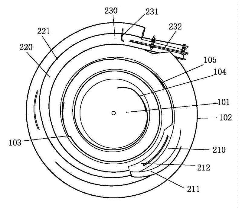
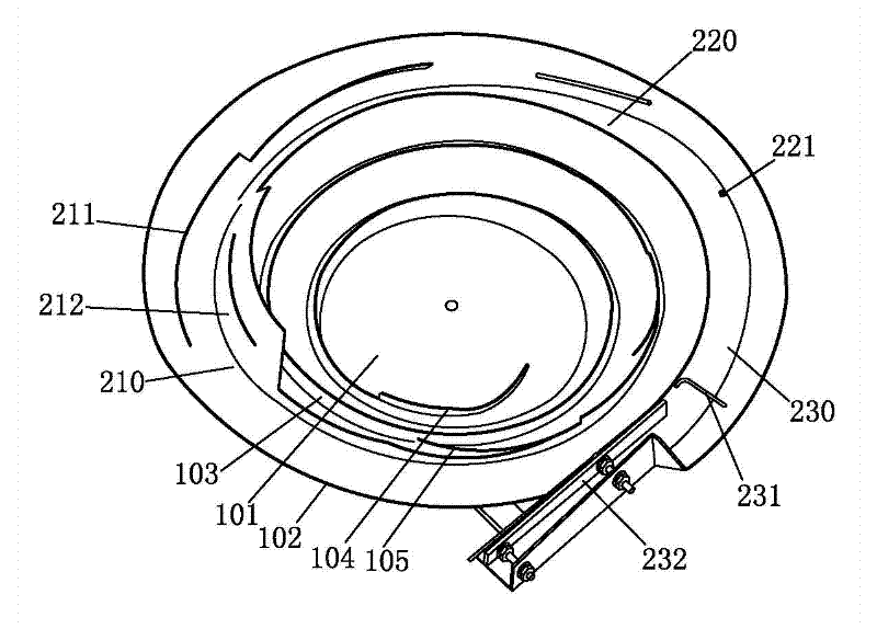
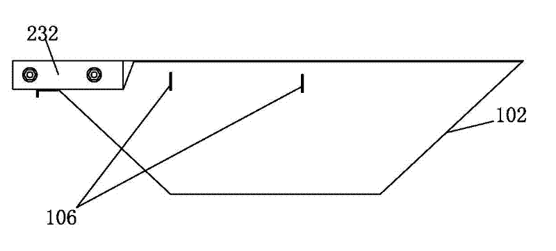
[0016] Such as figure 1 and figure 2 As shown, a material tray of an automatic feeding device includes a tray surface 101 and a side wall 102 surrounding the tray surface. There is a feeding track 103 spirally rising along the side wall 102, and the feeding end of the feeding track 103 is located at the lower part of the disk surface 101; , the end of the monolithic rail 200 protrudes from the side wall 102, and the discharge end of the loading rail 103 is connected to the feeding end of the monolithic rail 200. The monolithic rail 200 includes a turning section 210, a sorting section 220 and a sorting section 230.

[0017] The feed end of described feeding track 103 is provided with arc-shaped guide bar 104, and the front end of arc-shaped guide bar 104 is low and wide, and accessories are easily introduced in it, and the rear end of arc-shaped guide bar 104 is h...


PUM


Abstract

The invention relates to a feeding tray of an automatic feeding device, which includes a tray surface and a side wall surrounding the tray surface. A spirally rising feeding track is arranged on the inner side of the side wall, and the feeding end of the feeding track is located at a lower part of the tray surface. A monolithic track is extended from the discharge end of the track, and the monolithic track spirals up along the side wall, and the monolithic track includes at least a turning section, a sorting section and a sorting section. It has the advantages of reducing a large number of manual operations, improving work efficiency and reducing production costs.

Description

technical field [0001] The invention relates to automatic production of household electrical appliance accessories, in particular to a material tray of an automatic feeding device for household electrical appliance accessories. Background technique [0002] The accessories of household appliances, such as the synchronous motor housing, need to insert a shaft into the synchronous motor housing during processing. The traditional operation method is to manually insert the shaft into the synchronous motor housing by hand, and use a press to rivet the shaft. This requires a lot of workers to work semi-manually. This operation method greatly increases the cost of labor and cannot guarantee The quality of the shaft inserted into the timer housing often has problems such as loose shafts and uneven concentricity. To solve the problems, people hope to develop an automatic shaft riveting machine, which can carry out automated production, reduce labor costs and improve product quality; ...

Claims


Application Information

Patent Timeline
Patent Type & Authority Applications(China)
IPC IPC(8): B65G27/02B65G47/24B65G47/26
Inventor 刘洪彬杨陆军
Owner GUANGDONG GALANZ GRP CO LTD
Why Eureka
Try Eureka