Starter motors for use in starters of internal combustion engines

A technology for starting a motor and a starter, which is applied in the direction of motor starting for an engine, starting of an engine, machine/engine, etc., and can solve problems such as the danger of increasing friction

Inactive Publication Date: 2011-11-30
ROBERT BOSCH GMBH
View PDF7 Cites 5 Cited by
  • Summary
  • Abstract
  • Description
  • Claims
  • Application Information

AI Technical Summary

Problems solved by technology

thus risking increased friction

Method used


Image

  • Starter motors for use in starters of internal combustion engines
  • Starter motors for use in starters of internal combustion engines
  • Starter motors for use in starters of internal combustion engines

Examples


Embodiment Construction

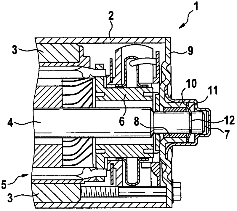
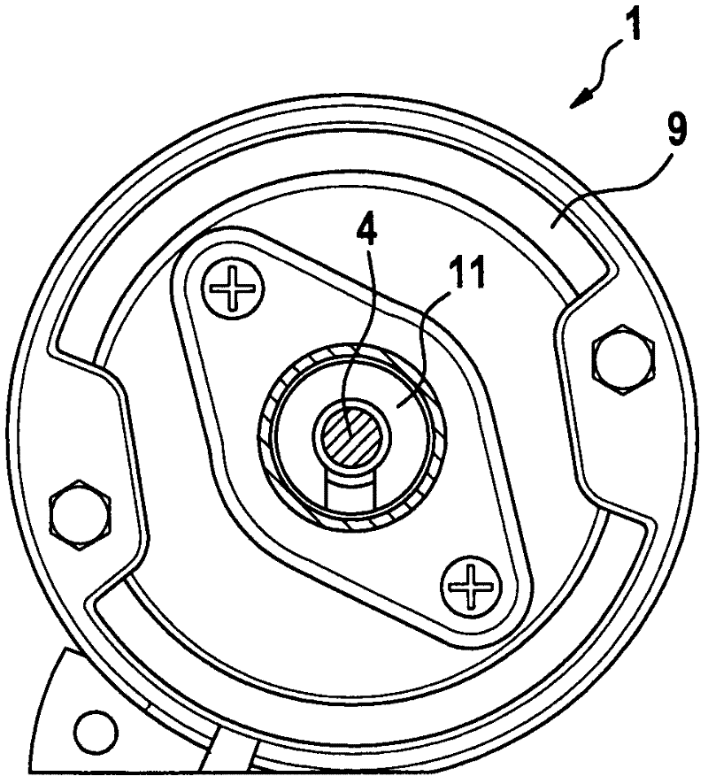
[0022] in accordance with figure 1 and figure 2 In the first embodiment of the present invention, an electric starter motor 1 is shown, which is an inner rotor motor and has a rotatably mounted drive shaft or armature shaft 4 in a motor housing or starter housing 2, said The housing has magnets arranged on the inside or pole pieces 3 with field windings. The drive shaft 4 is here, for example, a carrier for a starter pinion (not shown) which meshes in a comb-like manner with a gear wheel on the internal combustion engine. In other embodiments, the drive shaft first drives the planetary gears by means of the sun gear, which drive the starter pinion by means of the planetary carrier.

[0023] Inside the motor housing 2 , an armature 5 is pushed onto the drive shaft 4 , which armature has an armature iron plate made of laminations and an armature winding. The armature winding is energized via the commutator 6 , which comprises a slip ring fixedly connected to the drive shaft ...


PUM


Abstract

The motor (1) has a drive shaft (4) roatatably mounted at a bearing (8) in a starter housing (2). A longitudinal clearance compensator is provided for reduction of an axial clearance, and comprises a spring fixing element (11) that holds the shaft opposite to a housing component in a defined axial position. The fixing element is arranged in a region of the bearing. The fixing element causes force, which pulls the shaft with a commutator (6) toward to a bearing cap (9). The fixing element is designed as a ring connection plate in a disk shape.

Description

technical field [0001] The invention relates to a starter motor for use in a starter of an internal combustion engine according to the preamble of claim 1 . Background technique [0002] DE 32 16 448 A1 describes a starter device for an internal combustion engine which has a drive shaft with a drive pinion, wherein the drive shaft is connected to an armature mounted rotatably in an electric motor housing. An armature longitudinal play adjusting device with an axially adjustable screw, which abuts against the drive shaft at the end, is provided at the front end of the drive shaft. By adjusting the screw, the armature longitudinal clearance of the drive shaft can be influenced. [0003] In order to eliminate the longitudinal play of the armature, the screw of the adjusting device must be screwed in so that the screw and the drive shaft also come into contact with each other at the end faces during operation. There is thus a risk of increased friction. Contents of the inven...

Claims


Application Information

Patent Timeline
Patent Type & Authority Applications(China)
IPC IPC(8): F02N11/00F02N15/02
CPCF02N11/08F02N15/00F02N11/00F02N15/006H02K1/17H02K5/143H02K5/15
Inventor M·费尔恩
Owner ROBERT BOSCH GMBH
Why Eureka
Try Eureka