Electrically driven pump

A pump chamber and flow path technology, applied in the field of electric driven pumps, can solve problems such as affecting efficiency and incapable of shortening the length of the structure.

Inactive Publication Date: 2008-07-09
BSH BOSCH & SIEMENS HAUSGERAETE GMBH
View PDF9 Cites 0 Cited by
  • Summary
  • Abstract
  • Description
  • Claims
  • Application Information

AI Technical Summary

Problems solved by technology

The structural height of such a pump can only be reduced if the diameter of the rotating parts of the pump has to be reduced first, which in turn affects its efficiency
[0003] Another disadvantage of the conventional construction principle is that the shaft leading to the pump head must be reliably sealed in order to protect the motor from liquid escaping from the pump head
Although this pump does not have a rotating shaft and can realize the rotational fit between the motor and the pump head, it still cannot shorten the structural length of the pump along the axial direction.

Method used


Image

  • Electrically driven pump
  • Electrically driven pump
  • Electrically driven pump

Examples


Embodiment Construction

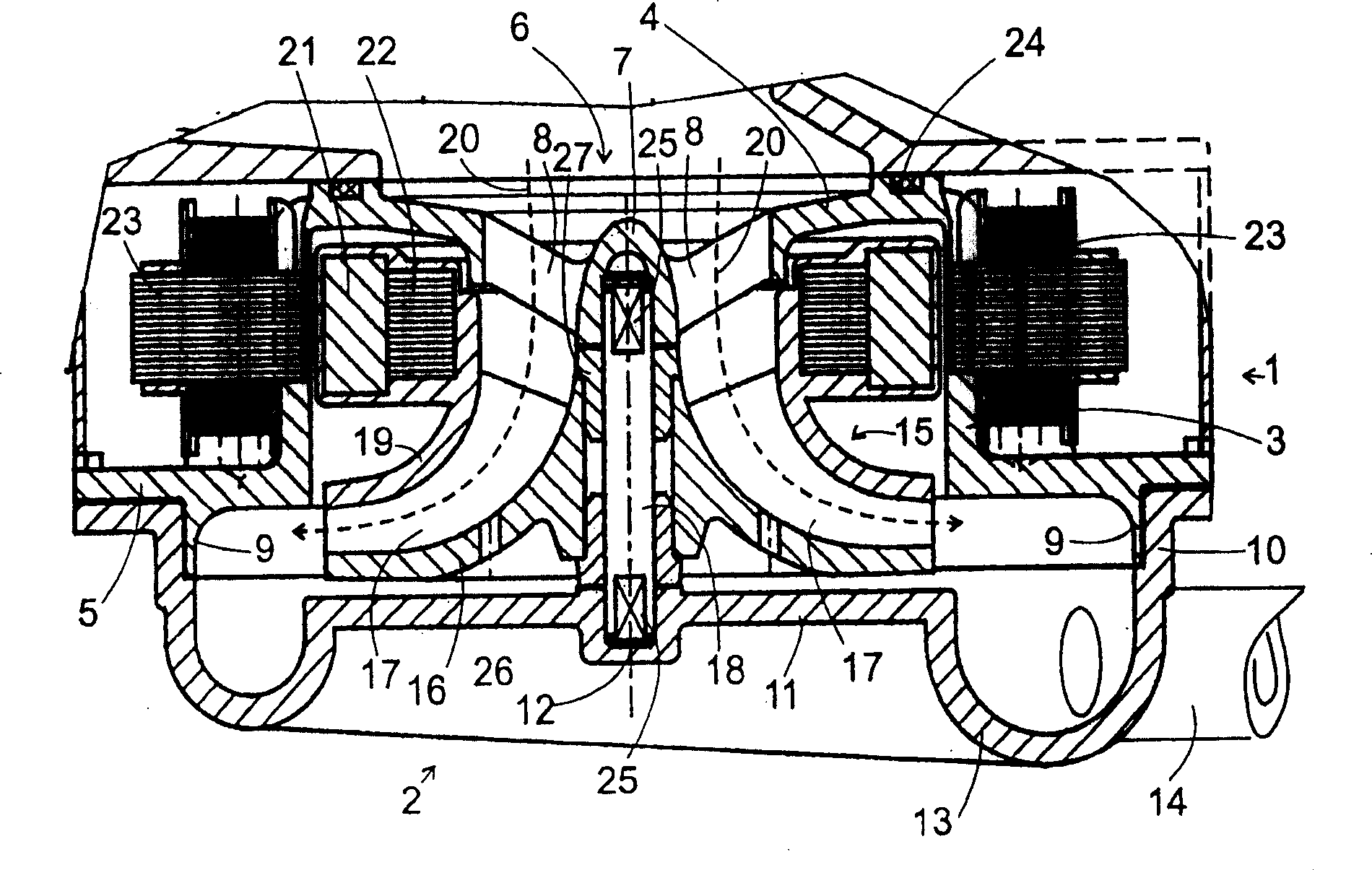
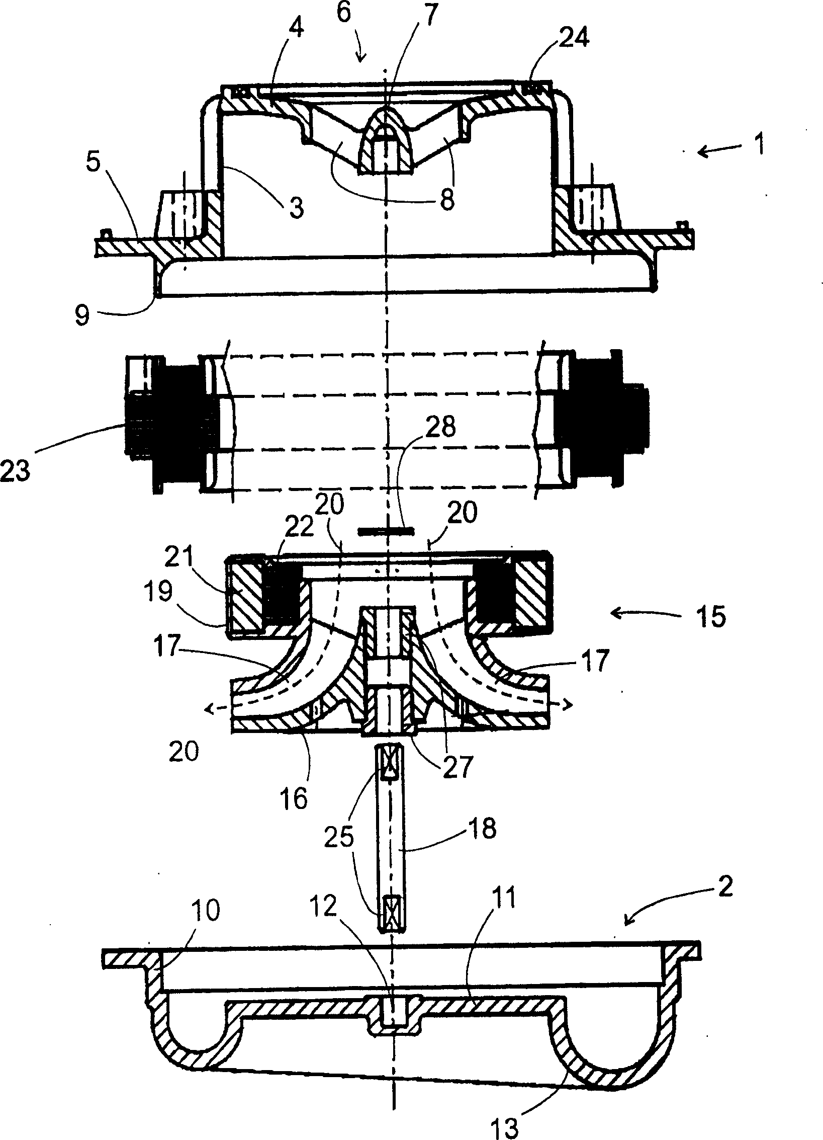
[0026] The housing of the pump consists of two parts 1 , 2 which are formed in one piece from plastic, for example by injection molding. The first housing part 1 has a cylindrical section 3 on both ends of which a shoulder 4 extending radially inwards with respect to the axis of the cylindrical section 3 and a shoulder extending radially outwards are formed 5. The inwardly extending shoulder 4 delimits an inlet 6 of the pump. In the center of the inlet opening 6 there is a socket 7 for a shaft 18 held by a support 8 which connects the socket 7 to the inwardly directed shoulder 4 .

[0027] On the side of the outwardly directed shoulder 5 facing away from the cylindrical section 3 a rib 9 is formed concentrically to the axis. The rib 9 has an inner surface that is uniformly bent into a quarter circle and a cylindrical outer surface on which a cylindrical outer wall 10 of the second housing part 2 fits. A second socket 12 is assigned to the opposite end of the shaft 18 on the...


PUM


Abstract

The invention relates to a pump comprising a pump chamber containing an impeller (15) and a rotor (21, 22) of an electrical machine, said rotor being connected to the impeller. A flow path (20) extends from the inlet (6) to the outlet (14) of the pump chamber through a central passage of the rotor (21, 22).

Description

technical field [0001] The invention relates to an electrically driven pump with an impeller rotating in a pump chamber. This type of pump is very versatile and can be used wherever liquid must be moved by a small back pressure, such as for swirling washing liquid in dishwashers or washing machines, as cooling water pumps on internal combustion engines, as water pumps on ships Bilge pumps, etc. Background technique [0002] Most pumps for liquids have a two-part construction with a motor for driving a shaft and a pump head driven by the shaft coupled to the motor in the longitudinal direction of the shaft. Such a device results in a construction of the pump that extends lengthwise in the direction of the shaft, which is not well suited to all installation situations in which such a pump can be used. For example, in a dishwasher, the pump for circulating the washing liquid is generally arranged below the rinsing chamber. The structural height of the pump should be as low a...

Claims


Application Information

Patent Timeline
IPC IPC(8): F04D29/04F04D13/06F04D29/041F04D29/043F04D29/047
CPCF04D13/0646F04D29/0413F04D29/047F04D29/043
Inventor M·卡拉夫斯基
Owner BSH BOSCH & SIEMENS HAUSGERAETE GMBH
Why Eureka
Try Eureka