A Composite Refrigeration System

A composite refrigeration and refrigeration cycle technology, applied in the direction of refrigerators, refrigeration components, refrigeration and liquefaction, etc., can solve the problems of low operating efficiency, lack of methods for supplying heat sources, high-temperature sensible heat not being further utilized, etc., to improve The effect of operating efficiency

Active Publication Date: 2011-11-30
SHANDONG UNIV
View PDF9 Cites 6 Cited by
  • Summary
  • Abstract
  • Description
  • Claims
  • Application Information

AI Technical Summary

Problems solved by technology

The system realizes the cascade coupling utilization of energy, but there are still many problems, such as the low operating efficiency of the system, the high-temperature sensible heat of the high-temperature and high-pressure refrigerant vapor formed after compression by the compressor has not been further utilized, and there is a lack of response Methods of supplying heat source issues, etc.

Method used


Image

  • A Composite Refrigeration System
  • A Composite Refrigeration System

Examples


Embodiment 1

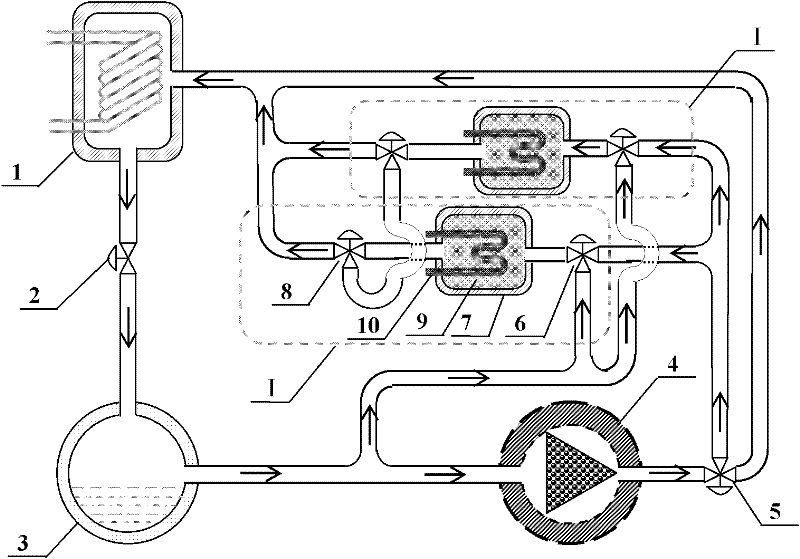
[0020] Such as figure 1 As shown, the present embodiment includes: condenser 1, throttle valve 2, evaporator 3, compressor 4, flow direction valve 5, adsorption unit 1 includes adsorption valve 6, adsorption bed 7 and desorption return quality valve 8, adsorption bed 7 Filled with adsorbent 9, the adsorption bed 7 is provided with a heat exchanger 10.

[0021] In this embodiment, the outlet of the adsorption valve 6 in the adsorption unit 1 is connected to the inlet of the adsorption bed 7, the outlet of the adsorption bed 7 is connected to the inlet of the desorption valve 8, and the lower ports of the desorption valve 8 in different adsorption units 1 are connected through pipelines to form Regeneration channel; the outlet of evaporator 3 is connected to the lower inlet of adsorption valve 6, the outlet of compressor 4 is connected to the inlet of flow direction valve 5, the right outlet of flow direction valve 5 is connected to the inlet of condenser 1, the upper outlet of ...

Embodiment 2

[0025] In this embodiment, the number of the adsorption units is four.

[0026] In this embodiment, the composite refrigeration system is driven by electric energy. When the compressor is running, the left port of the flow direction valve is connected to the upper port, and each adsorption unit goes through four states in turn: evaporation adsorption state, mass return state, compression thermal desorption state, and mass return state, completing a refrigeration cycle. During operation, one adsorption unit is always in the state of evaporation and adsorption, one adsorption unit is in the state of compression thermal desorption, and the two adsorption units are in the state of mass recovery.

[0027] The rest of the process of this embodiment is the same as that of Embodiment 1.

[0028] In this embodiment, the cooling efficiency (COP) of the system can be increased by 0.3-0.6.

Embodiment 3

[0030] In this embodiment, the number of the adsorption units is 3.

[0031] In this embodiment, the composite refrigeration system is driven by electric energy. All the adsorption units are closed, the compressor is running, and the left and right ports of the flow direction valve are connected to perform pure electric compression refrigeration.

[0032] The rest of the process of this embodiment is the same as that of Embodiment 1.


PUM


Abstract

The invention belongs to the technical field of refrigeration and discloses a composite refrigerating system, which comprises a condenser, a throttling valve, an evaporator, a compressor, a flowing valve and absorption units, wherein an outlet of the condenser is connected with an inlet of the throttling valve; the outlet of the throttling valve is connected with the inlet of the evaporator; the outlet of the evaporator is connected with the inlet of the compressor; the outlets of absorption valves in the absorption units are connected with the inlets of absorption beds; the outlets of the absorption beds are connected with the inlets of desorption mass recovery valves; lower openings of the desorption mass recovery valves in the different absorption units are communicated through a pipeline to form a mass recovery channel; the outlet of the evaporator is connected with lower inlets of the absorption valves; the outlet of the compressor is connected with the inlet of the flowing valve; a right outlet of the flowing valve is connected with the inlet of the condenser; an upper outlet of the flowing valve is connected with right inlets of the absorption valves; and left outlets of the desorption mass recovery valves are connected with the inlet of the condenser. The composite refrigerating system can perform independent driving or coupled driving by using heat energy and electricenergy, so that the stepped use of energy is realized; and mass recovery circulation is introduced, and part of heat which is carried by the steam of a high-temperature and high-pressure refrigerant is recovered, so that the operating efficiency of the system is effectively improved.

Description

technical field [0001] The invention belongs to the technical field of refrigeration, in particular to a refrigeration system combined with mechanical compression and adsorption. Background technique [0002] According to the data provided by the International Institute of Refrigeration, refrigeration and air-conditioning equipment alone consume about 15% of the world's electric energy, and the energy problems caused by the wide application of electric compression refrigeration devices have become increasingly prominent. After throttling in the electric compression refrigeration device, the liquid refrigerant enters the evaporator, absorbs the heat of the object to be cooled, and transforms it into low-pressure steam, and then compresses it into high-temperature and high-pressure steam through the compressor, and releases a large amount of heat after being cooled by the condenser. into a high-pressure liquid refrigerant to transfer heat from a low-temperature object to a hig...

Claims


Application Information

Patent Timeline
Patent Type & Authority Applications(China)
IPC IPC(8): F25B25/02F25B41/04
Inventor 赖艳华吕明新董震
Owner SHANDONG UNIV
Why Eureka
Try Eureka