Positioning, handling and assembly systems for manufacturing aerospace parts

一种航空零件、组装系统的技术,应用在航空零件的定位,处理和组装系统领域

Active Publication Date: 2011-11-30
AIRBUS OPERATIONS SL
View PDF5 Cites 4 Cited by
  • Summary
  • Abstract
  • Description
  • Claims
  • Application Information

AI Technical Summary

Problems solved by technology

It has very good structural properties and the manufactured pieces can be stored without any special conditions, but it also requires two curing cycles

Method used


Image

  • Positioning, handling and assembly systems for manufacturing aerospace parts
  • Positioning, handling and assembly systems for manufacturing aerospace parts
  • Positioning, handling and assembly systems for manufacturing aerospace parts

Examples


Embodiment Construction

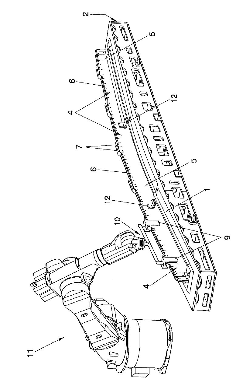
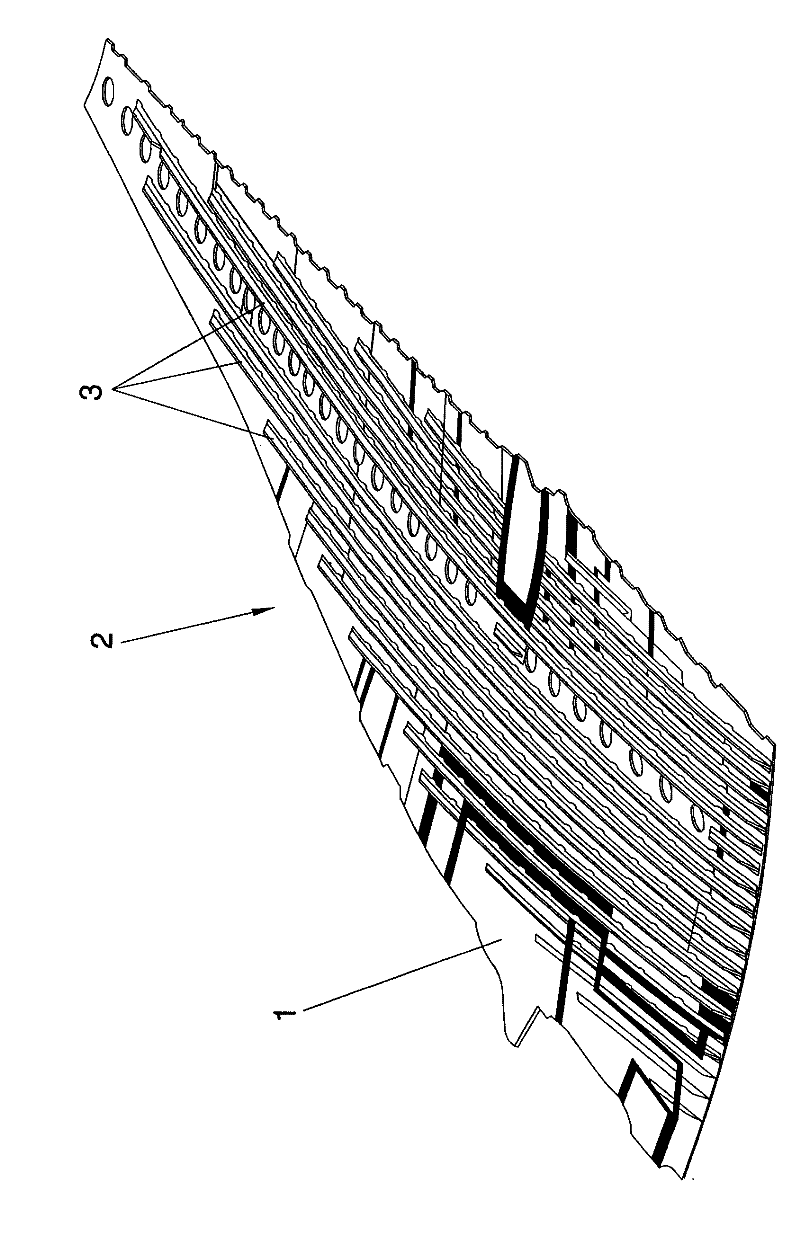
[0035] With reference to the reference numbers used in the attached drawings, we can see how the positioning, handling and assembly system for the manufacture of aerospace parts, which is the object of the present invention, achieves the purpose of finding the manufacture of such highly sophisticated parts, such as wings 2 hood 1 (see figure 1 ), wherein the lower surface of the hood 1 has an arrangement of longitudinal beams 3 having a "T"-shaped section fixed by cross members.

[0036] exist figure 2 , we see the geometry of the tool piece 4 used according to the invention and formed by two corner elements 5 and 6, one wing of the tool piece 4 (the horizontal one of the pair) resting against the cover 1, perfectly positioning itself adapted to its surface and the other wing facing and parallel to it, this distance corresponds to the thickness of the core of the stringer 3 (see Figure 4 ).

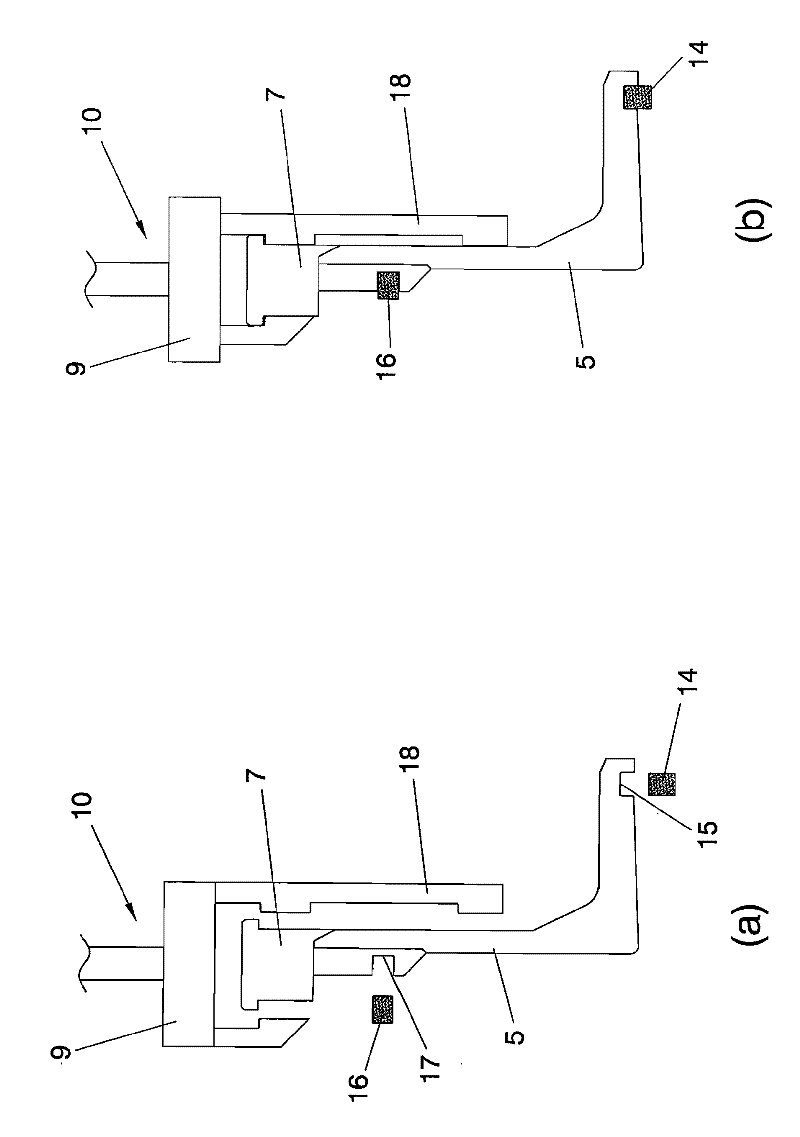
[0037] The corner elements 5 and 6 comprise on their top a pair of stacks 7 whic...


PUM


Abstract

The system has special application in the manufacture of aircraft wing covers (10 made of carbon fiber and the stringers (3) cured jointly with the wing cover during the polymerization in autoclave. The tool pieces (4) being used are defined by angular elements (5, 6) copying the geometry of the stringers (3). The shape of these stringers corresponds to the “T” section. The angular elements (5, 6) comprise, in their upper part, a pair of battlements (7) in order to be caught by part of the clamps (9) of a head (10) linked to a robot (11) of the spherical type with articulated arm with six axes. The angular elements (5, 6) are made of INVAR material and they are used to keep in position the stringers during the curing cycle in the autoclave.

Description

technical field [0001] As stated in the title of this descriptive specification, the present invention relates to a positioning, handling and assembly system for the manufacture of aerospace parts made of composite materials, which allows the preparation, including the positioning and take out. Background technique [0002] In recent decades, the introduction of advanced composite materials in the aerospace industry has received a major push to replace aluminum in the manufacture of large primary structures (including wings and stabilizers, lifting surfaces and fuselages) in commercial aircraft alloy. [0003] These composite structures (skins or shrouds formed from two-dimensional panels, commonly called skins) are not much different from their metallic precursors in that they are strengthened by beam-like elements (stringers) and in turn are reinforced by structural elements Braces, structural elements that maintain the geometry of the panels and provide a structure with...

Claims


Application Information

Patent Timeline
Patent Type & Authority Applications(China)
IPC IPC(8): B29C37/00B25J15/08
CPCB25J11/00B64C1/12B29D99/0014Y10T29/5184Y10T29/19Y10T29/49622B25J15/08B29C37/0007
Inventor J.M.桑托斯戈梅斯J.M.梅南德斯马丁A.杜兰奎罗加A.加西亚加西亚J.桑切斯弗南德斯
Owner AIRBUS OPERATIONS SL
Why Eureka
Try Eureka