
Shell and Tube Falling Film Evaporator

A falling-film evaporator and falling-film evaporation technology, applied in evaporation, chemical instruments and methods, separation methods, etc., can solve the problems of material filling, affecting the evaporation effect of the evaporator, and lack of materials, and achieve the effect of convenient connection

Inactive Publication Date: 2011-12-07
常熟市龙宇化工设备有限公司
View PDF10 Cites 11 Cited by
  • Summary
  • Abstract
  • Description
  • Claims
  • Application Information

AI Technical Summary

Problems solved by technology

Although the shell-and-tube falling film evaporator with this structure can avoid the damage to the heat exchange tube due to the direct welding of the liquid distributor and the heat exchange tube, the manufacture and installation are very troublesome.
Especially because the structure of the liquid distributor is still in the form of a tube head, in the actual use process, some of the heat exchange tubes in a group of heat exchange tubes (also called evaporation tubes) are full of materials, and some of the heat exchange tubes are full of materials. Insufficient material or even lack of material in the tube will affect the evaporation effect of the evaporator

Method used


Image

  • Shell and Tube Falling Film Evaporator
  • Shell and Tube Falling Film Evaporator
  • Shell and Tube Falling Film Evaporator

Examples


Embodiment Construction

[0015] In order to enable the examiners of the patent office, especially the public, to understand the technical essence and beneficial effects of the present invention more clearly, the applicant will describe in detail the following in the form of examples, but none of the descriptions to the examples is an explanation of the solutions of the present invention. Any equivalent transformation made according to the concept of the present invention which is merely formal but not substantive shall be regarded as the scope of the technical solution of the present invention.

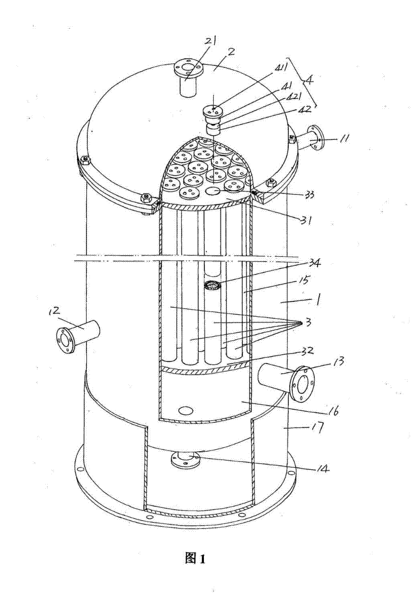
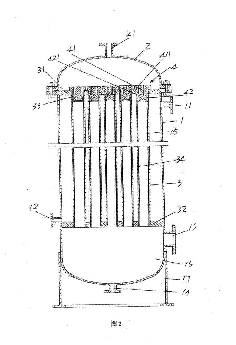
[0016] See figure 1 and figure 2 , a tank body 1 is given, the tank body 1 can also be referred to as a cylinder body, a steam introduction port 11 is fixedly connected to the side wall of the upper part of the tank body 1, and a steam inlet port 11 is fixed on the side wall of the lower part of the tank body 1 A steam condensate outlet port 12 (ie, condensed water outlet port) is fixedly connected, a...


PUM


Abstract

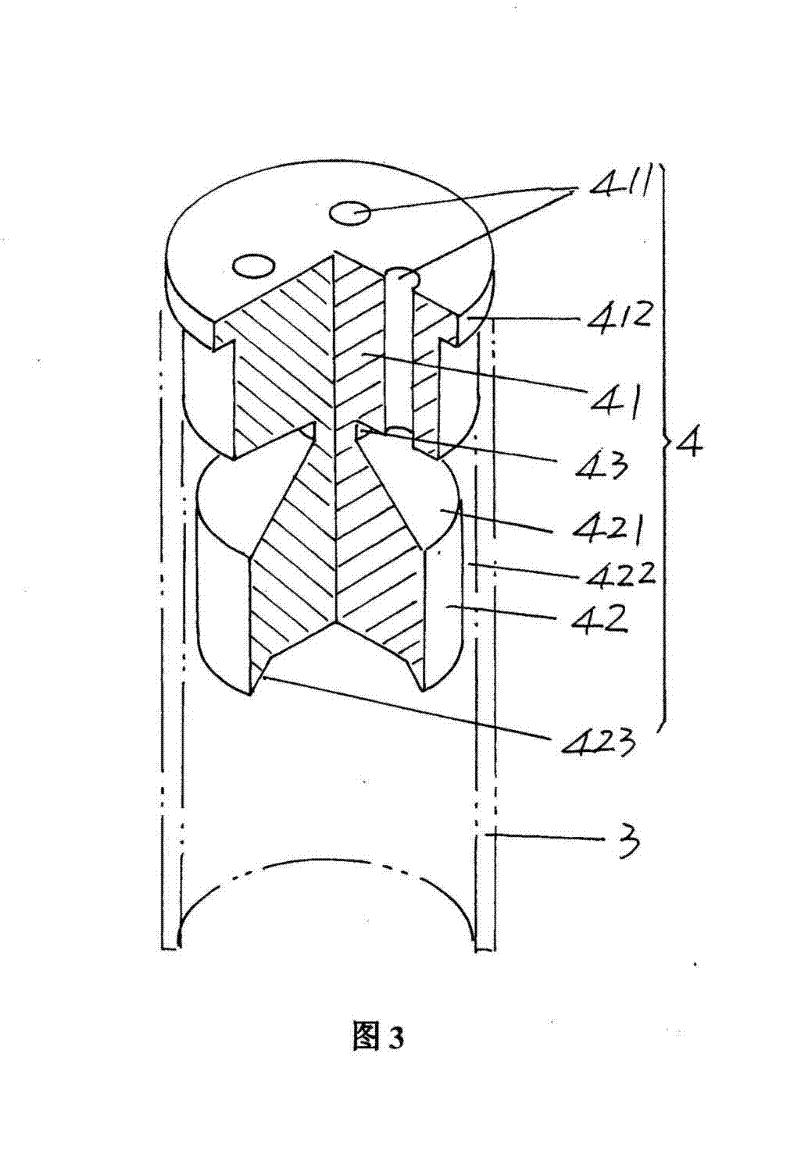
A shell-and-tube falling film evaporator belongs to the technical field of biomedicine and chemical equipment. It includes a tank body equipped with a steam inlet port, a steam condensate outlet port, a secondary steam outlet port and a concentrated liquid outlet port, a tank cover arranged on the upper part of the tank body, a set of falling film evaporation tubes arranged in the tank body and configuration The liquid distributor at the mouth of each falling film evaporation tube is characterized by: the liquid distributor includes the first and second column sections, a set of liquid distribution holes is opened on the first column section, and a set of liquid distribution holes is opened on the second column section. A liquid guide slope is formed on one end of the section, the diameter of the second column section is smaller than that of the first column section, and the flange edge of the liquid distributor is expanded on the edge of the top of the first column section, and the liquid distributor The flange edge is matched with the nozzle of the falling film evaporation tube, and there is a liquid gap between the second column section and the inner wall of the evaporation tube of the falling film evaporation tube. Advantages: It can ensure the uniformity of the liquid film to improve the evaporation effect of the evaporating tube; it will not damage the evaporating tube, and the connection between the entire liquid distributor and the evaporating tube is very convenient.

Description

technical field [0001] The invention belongs to the technical field of biomedicine and chemical equipment, and in particular relates to a shell-and-tube falling film evaporator. Background technique [0002] Shell-and-tube falling film evaporators are usually called falling film evaporators, and then called thin film evaporators. The evaporators of this structure can be found in a large number of published Chinese patent documents, such as CN201618431U ( falling film evaporator), CN101954195A (a falling film evaporator) and CN102107091A (a multi-stage high-efficiency horizontal tube falling film evaporator). [0003] A typical shell-and-tube falling film evaporator is disclosed by utility model patent authorization announcement numbers CN201880383U and CN201840900U. In the background technology of CN201880383U, it is pointed out that the liquid distributor (also called distributor) is a key in the shell-and-tube falling film evaporator The structure of the liquid distributo...

Claims


Application Information

Patent Timeline
Patent Type & Authority Applications(China)
IPC IPC(8): B01D1/22
Inventor 吕鸣冈张建龙
Owner 常熟市龙宇化工设备有限公司
Learn More