Ultra-high speed cutting three-dimensional dynamic force test platform

A three-dimensional dynamic and test platform technology, applied in the direction of measuring/indicating equipment, metal processing machinery parts, metal processing equipment, etc., can solve problems such as vibration mode interference, natural frequency drop, strong nonlinear vibration interference, etc., to achieve reliable work , Simple structure, low cost effect

Inactive Publication Date: 2011-12-07
NANJING UNIV OF AERONAUTICS & ASTRONAUTICS
View PDF9 Cites 23 Cited by
  • Summary
  • Abstract
  • Description
  • Claims
  • Application Information

AI Technical Summary

Problems solved by technology

However, when cutting at ultra-high speeds, the cutting force presents a high-frequency discontinuity. Under the excitation of the high-frequency discontinuity of the cutting force, the main low-order modes of the processing system are mixed with each other, and the measured force signal strongly disturbed by the structure's own vibration modes
[0003] Most of the existing cutting dynamometers have a natural frequency within 1-5KHz, and after installing tools or parts, the natural frequency of the dynamometer system will further decrease, which cannot meet the impact frequency of 0.5 when cutting at ultra-high speeds. Accurate measurement of ~3KHz milling force signal
In addition, due to the strong nonlinear interference of vibration during ultra-high speed cutting, it is extremely difficult to obtain accurate ultra-high speed cutting force signals, which brings great challenges to the study of material deformation mechanism and ultra-high speed cutting tribology. big challenge

Method used


Image

  • Ultra-high speed cutting three-dimensional dynamic force test platform
  • Ultra-high speed cutting three-dimensional dynamic force test platform

Examples


Embodiment Construction

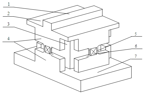
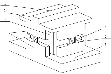
[0017] The structure and working process of the present invention will be described in detail below in conjunction with the accompanying drawings.

[0018] Such as figure 1 As shown, the present invention provides a three-dimensional dynamic force test platform for ultra-high-speed cutting, which is an integral structure directly processed from a block-shaped blank of the processed material and affixed with a group of resistance strain gauges, including a structure to be cut 1 , upper surface platform 2, elastic cylinder 3, elastic slab 4, elastic sheet 5, resistance strain gauge group 6 and support base 7, wherein, support base 7 is positioned at the bottom, plays a supporting role; elastic cylinder 3 Located on the support base 7, in this embodiment, the elastic cylinder 3 is located at the center of the support base 7, and in consideration of the processing cost, a regular square prism structure is adopted; eight elastic slabs 4 are designed, of which two elastic slabs 4 ...


PUM


Abstract

The invention discloses a three-dimensional dynamic force test platform for ultra-high-speed cutting, which includes a structure to be cut, four resistance strain gauge groups, an integrally formed upper surface platform, an elastic cylinder, eight elastic thick slices, four elastic thin slices, a support The base; the elastic cylinder is located on the supporting base; 8 elastic slabs are in pairs, 4 elastic sheets correspond to 4 groups of elastic slabs one by one, and the two ends of the elastic sheets are respectively connected to two elastic slabs in each group. One end of the sheet constitutes 4 elastic groups, and the 4 elastic groups are respectively located around the elastic cylinder, and the other ends of the two elastic slabs in each elastic group are respectively connected to the support base and the upper surface platform; the upper surface platform is located on The upper part of the elastic cylinder and the elastic group is connected with the elastic cylinder; the structure to be cut is arranged on the upper surface platform; the resistance strain gauge group is respectively fixed at the middle position of the four elastic sheets. This kind of test platform can meet the requirements of ultra-high speed cutting force signal measurement, and realize the accurate measurement of three-dimensional dynamic force.

Description

technical field [0001] The invention relates to a cutting force testing device, in particular to an integral high-frequency-response ultra-high-speed cutting three-dimensional dynamic force testing platform with high natural frequency. Background technique [0002] The cutting force signal is an important state parameter in the cutting process, and the detection of the cutting force signal is one of the most researched and applied cutting process monitoring methods at home and abroad. With the rapid development of ultra-high-speed cutting technology, especially the ultra-high-speed milling technology based on high-frequency electric spindle, the cutting behavior of ultra-high-speed cutting has attracted more and more attention. Accurate acquisition of ultra-high-speed cutting force signals is the basic experimental guarantee for the study of ultra-high-speed cutting deformation and cutting friction, and is a key link necessary for establishing ultra-high-speed cutting equa...

Claims


Application Information

Patent Timeline
Patent Type & Authority Applications(China)
IPC IPC(8): B23Q17/09
Inventor 赵威何宁李亮孙永华杨吟飞
Owner NANJING UNIV OF AERONAUTICS & ASTRONAUTICS
Why Eureka
Try Eureka