
Internal combustion engine sector cylinder

An internal combustion engine and fan-shaped technology, which is applied to internal combustion piston engines, combustion engines, mechanical equipment, etc., can solve the problems of high internal consumption power, low efficiency of cylinder work, and many moving parts.

Inactive Publication Date: 2011-12-07
丁旭
View PDF4 Cites 0 Cited by
  • Summary
  • Abstract
  • Description
  • Claims
  • Application Information

AI Technical Summary

Problems solved by technology

One of the main reasons for the loss of work efficiency is that there are many moving parts and high internal power consumption when doing work. During the century of the invention and development of the internal combustion engine, this piston-type cylinder has not changed substantially, so the work efficiency of the cylinder can not be improved.

Method used


Image

  • Internal combustion engine sector cylinder
  • Internal combustion engine sector cylinder

Examples


Embodiment Construction

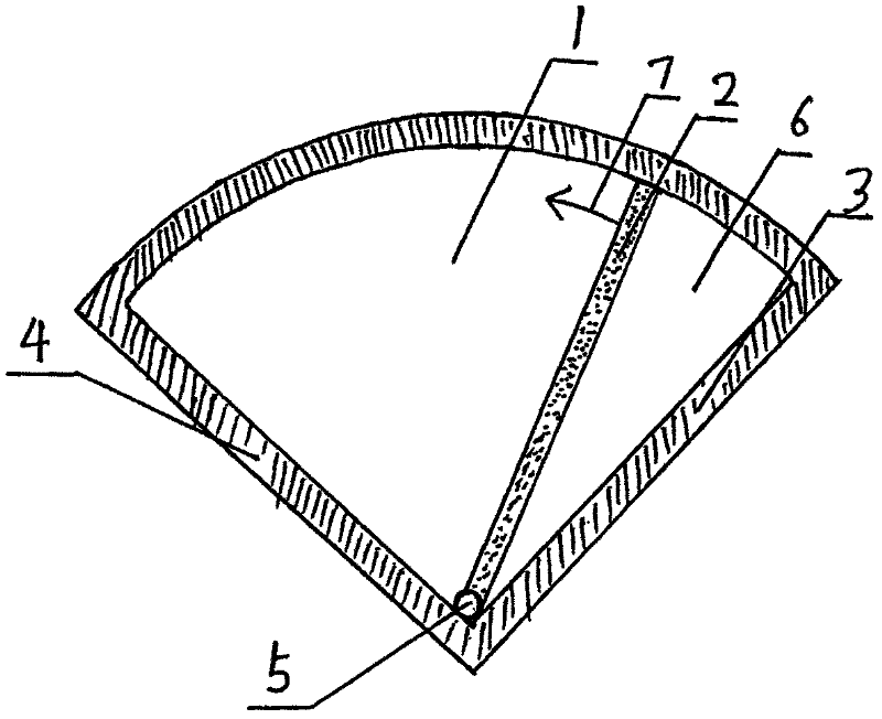
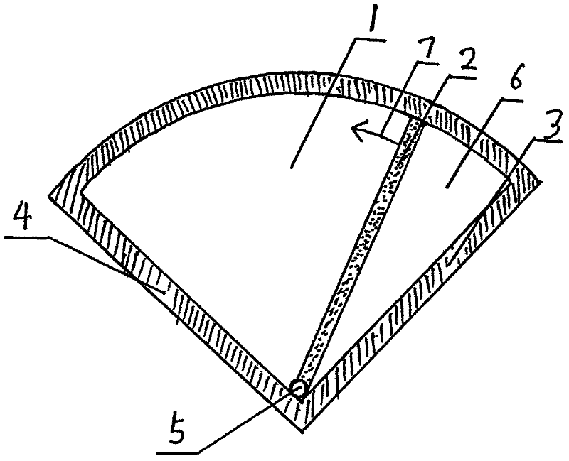
[0008] In the invention, a leaf-shaped shutter is installed in the fan-shaped cylinder, the shutter shaft is installed at the intersection of the two ends of the cylinder, and the moving parts only have the shutter when doing work, so the structure is very simple. Since only the valve is in contact with the cylinder, the frictional resistance is very small when the work is done, the moving parts are few when the work is done, and the mass of the moving parts is also reduced, which improves the efficiency of the internal combustion engine.


PUM


Abstract

The invention relates to a fan-shaped cylinder for combustion and work of an internal combustion engine. The device is composed of a sector cylinder, a leaf valve and a valve shaft. The main features are: in the fan-shaped cylinder, the leaf valve is on the axis at the angle between the combustion end and the exhaust end. When doing work and burning, the leaf valve does fan-shaped reciprocating motion in the fan-shaped cylinder. The invention reduces the frictional resistance and moving mass of the moving parts when the internal combustion engine works and burns, and improves the efficiency of the internal combustion engine.

Description

Technical field: [0001] The present invention is a device for combustion and work of an internal combustion engine Background technique: [0002] There are two main types of internal combustion engines: piston-type and rotor-type cylinders. Rotary engines are complex in structure, expensive to manufacture, and have few practical applications. Four-stroke piston internal combustion engines are mainly used in daily life. Although this kind of internal combustion engine is complicated to manufacture, its technology is mature. Internal combustion engine efficiency is about 25% - 40%. One of the main reasons for the loss of work efficiency is that there are many moving parts when doing work, and the internal power consumption is large. During the hundred years of the invention and development of the internal combustion engine, this kind of piston cylinder has not changed substantially, so the work efficiency of the cylinder is not always improved. . Invention content: [00...

Claims


Application Information

Patent Timeline
IPC IPC(8): F02B55/08F02B55/02F02B23/00
CPCY02T10/125Y02T10/12
Inventor 丁旭
Owner 丁旭
Learn More