Check patentability & draft patents in minutes with Patsnap Eureka AI!

Simulator for simulating resolver output signals

A resolver and output signal technology, which is applied in the testing of machines/structural components, instruments, vehicles, etc., can solve the problems of inability to test in extreme conditions, large motor wear, and inconvenient testing, etc., and achieves amplitude and speed settings Convenient, easy to use, easy to develop effects

Inactive Publication Date: 2011-12-07
SHANGHAI JINMAI ELECTRONICS TECH
View PDF2 Cites 9 Cited by
  • Summary
  • Abstract
  • Description
  • Claims
  • Application Information

AI Technical Summary

Problems solved by technology

Therefore, the test of ECU is also particularly important. The traditional test method is to build a bench, install a motor, a motor controller and a resolver, and use the motor to drive the resolver so that the resolver outputs a resolver signal to the ECU. Analysis, the disadvantages of doing this are: the wear and tear on the motor is relatively large, the test range is narrow, the extreme conditions cannot be tested, the risk factor is relatively high, the space is large, and the test is inconvenient

Method used


Image

  • Simulator for simulating resolver output signals
  • Simulator for simulating resolver output signals
  • Simulator for simulating resolver output signals

Examples


Embodiment Construction

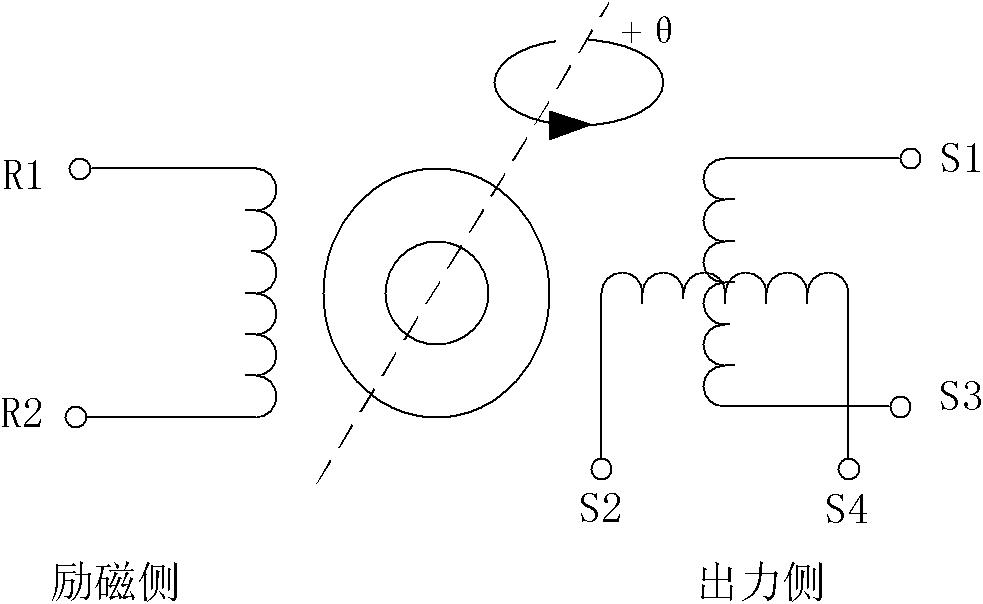
[0013] In order to better understand the present invention, the working principle of the resolver will be described in detail below. Such as figure 1 As shown, when the motor drives the resolver to rotate, the primary side voltage of the resolver is: U R1-R2 =E sin wt, the secondary side voltage is: U s4-s2 = KE sin wt sin θ, U s3-s1 =KE sin wt cosθ, according to the relationship between the primary side voltage and the secondary side voltage, the relationship between the rotor position angle θ and the rotational speed can be obtained as θ=2πNt / 60+C, where N is the rotational speed and C is a constant, then the sinusoidal resolver signal The waveform relation is U s4-s2 =KE sin wt sinθ=KE sin wt sin(2πNt / 60+C), the waveform relationship of the cosine resolver signal is U s3-s1 =KE sin wt cos θ=KE sin wt cos(2πNt / 60+C).

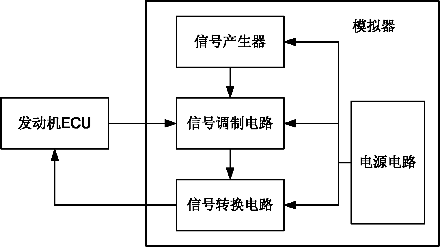
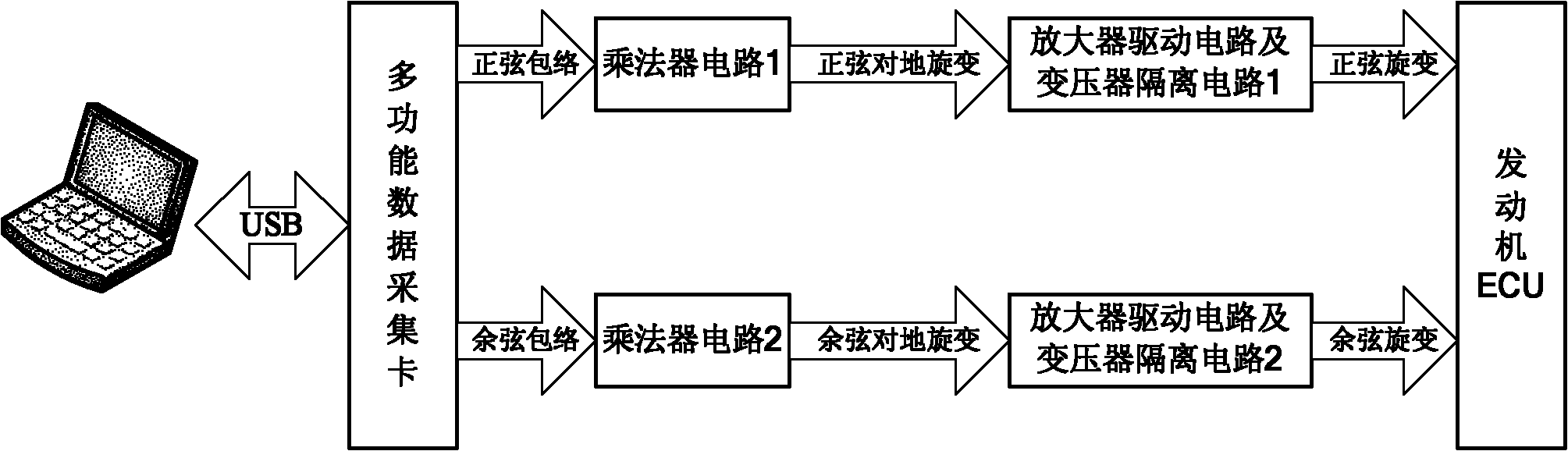
[0014] In order to simulate the resolver signal output by the above-mentioned resolver, the simulator for simulating the output signal of the resolver of...


PUM


Abstract

The simulator for simulating the output signal of the rotary transformer provided by the present invention includes: a signal generator for generating two-way analog trigonometric function signals based on preset signal amplitudes and rotating speeds; A signal modulation circuit that modulates the input baseband signal to form two resolver signals to the ground; it is used to convert the two resolver signals to the ground to simulate the differential resolver signal output by the resolver The signal conversion circuit; and the power circuit. The simulator has the advantages of wide measurable speed range, small space, zero wear of the motor, good portability, and convenient use.

Description

technical field [0001] The invention relates to the field of automobile testing, in particular to a simulator for simulating the output signal of a resolver. Background technique [0002] At present, the electronic control unit (ECU) of the automobile is the core technology of the electronic control system of the automobile. Its main function is to calculate, process, and judge the information input by various sensors according to the internal programs and data, and then output instructions. Therefore, the test of ECU is also particularly important. The traditional test method is to build a bench, install a motor, a motor controller and a resolver, and use the motor to drive the resolver so that the resolver outputs a resolver signal to the ECU. According to the analysis, the disadvantages of doing this are: the wear and tear on the motor is relatively large, the test range is narrow, the extreme conditions cannot be tested, the risk factor is relatively high, the space is l...

Claims


Application Information

Patent Timeline
Patent Type & Authority Applications(China)
IPC IPC(8): G01M17/007
Inventor 康兵韩伟段立卿王银杉
Owner SHANGHAI JINMAI ELECTRONICS TECH
Features
  • R&D
  • Intellectual Property
  • Life Sciences
  • Materials
  • Tech Scout
  • Unparalleled Data Quality
  • Higher Quality Content
  • 60% Fewer Hallucinations
Learn More