variable gain amplifier

An amplifier and operational amplifier technology, applied in the field of circuits, can solve the problems of non-constant step size, large deviation, low linearity of variable gain amplifier, etc., and achieve the effect of reducing influence and improving accuracy

Inactive Publication Date: 2011-12-07
SHANGHAI XINPUZHEN MICROELECTRONICS
View PDF5 Cites 22 Cited by
  • Summary
  • Abstract
  • Description
  • Claims
  • Application Information

AI Technical Summary

Problems solved by technology

However, the variable gain amplifier used in this patent is an open-loop structure, so the linearity of the variable gain amplifier is low
[0009] On the other hand, since the on-resistance between the source and drain of the transistor

Method used


Image

  • variable gain amplifier
  • variable gain amplifier
  • variable gain amplifier

Examples


Embodiment Construction

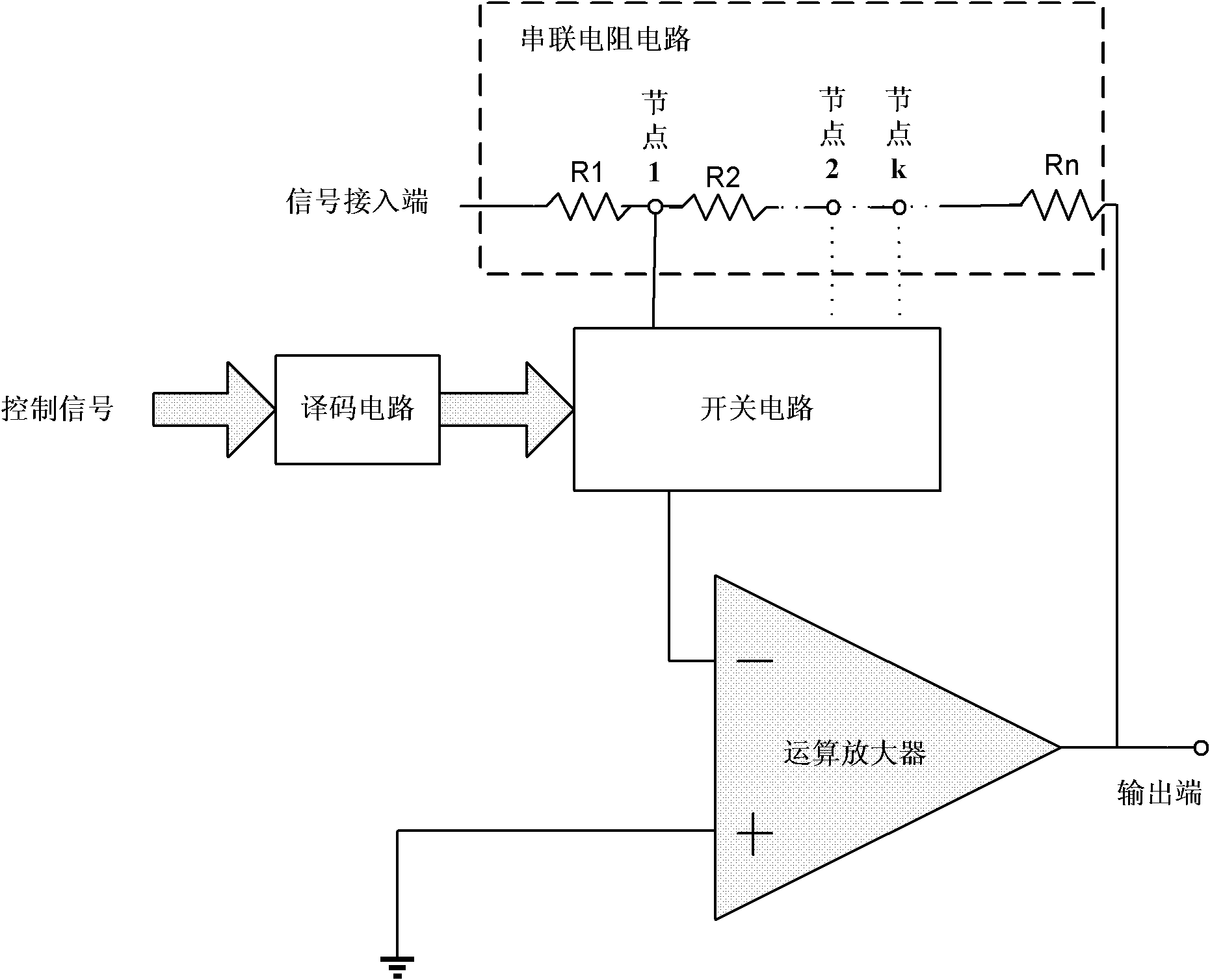
[0021] see figure 2 , The variable gain amplifier of the present invention includes: an operational amplifier, at least one series resistance circuit, a switch circuit and a decoding circuit. in, figure 2 Only one series resistance circuit is shown, but those skilled in the art should understand that, in fact, the number of series resistance circuits included in the variable gain amplifier may be 2 or more.

[0022] The operational amplifier is preferably an amplifier with a DC gain of not less than 60 dB in order to improve the accuracy of gain adjustment, for example, a two-stage Miller type operational amplifier in a CMOS process may be used.

[0023] One end of each series resistance circuit is used as a signal input end, and the other end is connected to the output end of the operational amplifier, which is a series resistance circuit formed by a plurality of resistances connected in series. E.g, figure 2 The series resistor circuit shown is composed of resistors R1...


PUM


Abstract

The present invention provides a variable gain amplifier, which includes: an operational amplifier; at least one series resistor circuit with one end as a signal input end and the other end connected to the output end of the operational amplifier, and a plurality of resistors connected in series; and A switch circuit connected to multiple nodes of each series resistor circuit and an input terminal of the operational amplifier is used to control the on-off of multiple nodes of each serial resistor circuit and an input terminal of the operational amplifier, so that each Part of the resistance in a series resistance circuit is used as the input resistance of the operational amplifier, and the rest of the resistance is used as the feedback resistance of the operational amplifier; and a decoding circuit is used to decode the input control signal and output it for controlling the operational amplifier. The opening and closing signals of the opening and closing of the plurality of controlled switches. The invention has the advantages of removing the switch circuit from the signal path, thereby eliminating the influence of the on-resistance of each switch on the input impedance and feedback impedance of the operational amplifier, and improving the linearity of the gain.

Description

technical field [0001] The invention relates to the field of circuits, in particular to a variable gain amplifier. Background technique [0002] In modern wireless communication technology, due to the uncertainty of received signal power, automatic gain control has become an important module in the communication system, and the variable gain amplifier is the core of the automatic gain control loop. The automatic gain control loop adjusts the gain control signal of the variable gain amplifier to stabilize the amplitude of the output signal within a range without being affected by the amplitude of the input signal, thereby reducing the difficulty of subsequent circuit processing signals. Linearity, low noise, low power consumption, high bandwidth, and a linear relationship with the gain control signal in dB are all basic requirements for a variable gain amplifier. [0003] The following are two commonly used gain variable amplifier structures: [0004] The first type: see f...

Claims


Application Information

Patent Timeline
IPC IPC(8): H03G3/20
Inventor 闫涛涛沈晓斌周健军
Owner SHANGHAI XINPUZHEN MICROELECTRONICS
Why Eureka
Try Eureka