
Multi-storey mechanical parking system

A mechanical parking, multi-layer structure technology, applied in the field of parking systems, can solve the problems of considerable maintenance costs, complexity of control systems, and complex systems.

Inactive Publication Date: 2011-12-07
白闰康
View PDF5 Cites 7 Cited by
  • Summary
  • Abstract
  • Description
  • Claims
  • Application Information

AI Technical Summary

Problems solved by technology

However, on the opposite side with such characteristics, these systems need to complete power transmission and conversion with one structure. Therefore, elevators and left-right conversion plus complicated power conversion and power transmission devices present a problem that some systems become complicated.
The complexity of the system eventually leads to the complexity of the control system, and maintenance requires considerable costs

Method used


Image

  • Multi-storey mechanical parking system
  • Multi-storey mechanical parking system
  • Multi-storey mechanical parking system

Examples


Embodiment Construction

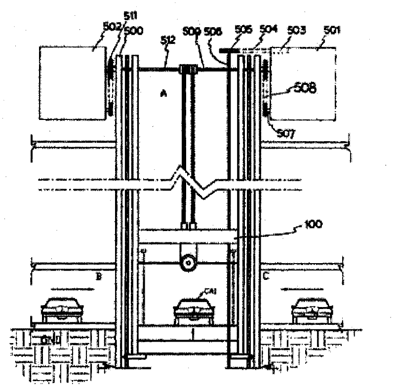
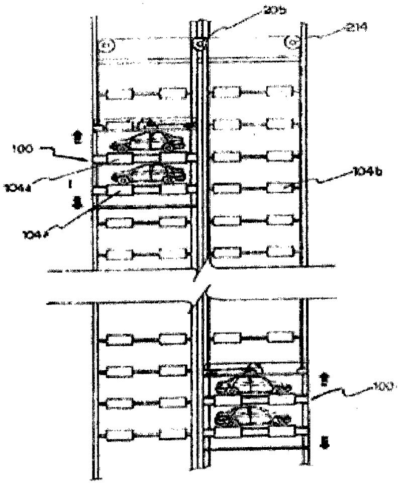
[0034] The invention provides a multi-level horizontal and vertical circulation mechanical parking system unitized, which is easy to assemble and maintain on site.

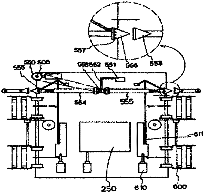
[0035] The present invention is basically developed by integrating the entry and exit control unit 1000 and the entry and exit movement unit 1500 that receives power from the left and right clutches 301 and 302 of the entry and exit control section and moves the parked vehicle moving from the entry and exit dual-purpose parking section to the left and right. The unitized transfer structure. Furthermore, the entrance and exit combined parking section that transfers the vehicle to the left and right is integrally formed on the left and right sides of the entrance and exit control section and the entrance and exit moving section, and the entrance and exit of the vehicle are performed by separate operations. In addition, the entrance and exit dual-purpose parking part and the transfer structure for upward and downward...


PUM


Abstract

The present invention relates to multilayered, mechanical parking systems. Specifically, the present invention is a new parking system which facilitates installation and maintenance by compartmentalization. The main structure of a conventional mechanical parking system loads a vehicle on a pallet and parks the vehicle on a required spot, regardless of parking style such as horizontal circulation type, vertical circulation type, or mixed type. Such a pallet system comprises: a pallet structure which loads the vehicle and circulates vertically or horizontally in addition to an existing parking pallet; and a complex apparatus for operation to enable the pallet structure to unload or load the vehicle onto a required place. Particularly, the pallet is pulled or released by a wire in order to load and convey the vehicle while keeping the pallet balanced horizontally. Accordingly, if winding and releasing the wire cannot be controlled precisely, or if a sensor or a motor malfunctions, a serious problem may occur. To improve on the disadvantages mentioned above, the present inventor uses a conveyor belt to move the vehicle horizontally and vertically to park the vehicle into a targeted place in Korean patent Application No. 95-15882 and Korean Patent No. 403484. Accordingly, installation and maintenance using such a parking system has been improved to be easier than using a parking system of a pallet structure. Korean Patent No. 10-2008-136500 discloses a moving unit which moves a vehicle horizontally when the vehicle enters for parking. The present invention compartmentalizes the moving unit to enable the moving unit to move vertically. Thereby, a unit which moves horizontally and parks the vehicle may be systematically installed using a self-assembly method. Also, a conveyor belt may be installed with an arbitrarily adjusted length thereof as upper and lower members of the conveyor belt are assembled using a pin-fixing method. A power generating unit, a power transferring unit, a power transforming unit, etc. may be added or removed freely regardless of the number of vehicles or the required area because the power generating unit, power transferring unit, power transforming unit, etc., are assembled as one unit. The present invention improves on the above Korean patent application further. The present invention allows precise control of both sides of the conveyor belt using an input / output controller, and comprises the compartmentalized input / output controller in a multilayered structure.

Description

technical field [0001] The present invention relates to a multi-storey mechanical parking device, in particular to a parking system, which separates the storage part and the storage part of the vehicle to be parked, and independently operates the lifting transfer part that moves up and down, not only can move up and down the most Vehicles that are quickly put into storage can also be moved horizontally. Background technique [0002] In the inventor's registered patent 10-0403484, a parking tower system has been developed, including: a power generating part, which is formed in the central transfer channel A of the parking system that is formed as a multi-storey structure through the horizontal and vertical members. The upper end of one side is provided with a power generating device, and the power generated by the power generating device is transmitted to the main drive shaft extended to the lowermost end of the central transfer channel and the traction drive shaft arranged h...

Claims


Application Information

Patent Timeline
Patent Type & Authority Applications(China)
IPC IPC(8): E04H6/18
CPCE04H6/22E04H6/14E04H6/18
Inventor 白闰康
Owner 白闰康
Learn More