Optical information analyzing device and optical information analyzing method

A technology of an analysis device and an analysis method, applied in the field of optical information analysis devices, can solve the problems of deviation in optical information, inability to adjust the optical axis of an irradiating part, scattered light and reduced fluorescence sensitivity, etc.

Active Publication Date: 2011-12-07
雅马拓科学株式会社
View PDF5 Cites 4 Cited by
  • Summary
  • Abstract
  • Description
  • Claims
  • Application Information

AI Technical Summary

Problems solved by technology

[0005] However, in the above-mentioned conventional device, there is a problem that when the sample flow passes through a position deviated from the center of the flow path in the flow cell, the optical axis of the irradiating part coincides with the sample flow. The optical axis of the optical system of the part does not cross the optical axis of the sample flow and the irradiation part
Therefore, the light receiving unit is configured to receive light in a wide range. As a result, the sensitivity of detected scattered light and fluorescence decreases, or the obtained optical information of the specimen varies.
[0006] In addition, there is a problem that the optical axis of the irradiation part cannot be adjusted and the optical axis of the irradiation part cannot be adjusted easily because the sample flow is actually produced only by flowing the liquid in the flow channel in the flow cell.

Method used


Image

  • Optical information analyzing device and optical information analyzing method
  • Optical information analyzing device and optical information analyzing method
  • Optical information analyzing device and optical information analyzing method

Examples


Embodiment Construction

[0081] Hereinafter, embodiments of the present invention will be described in detail based on the drawings.

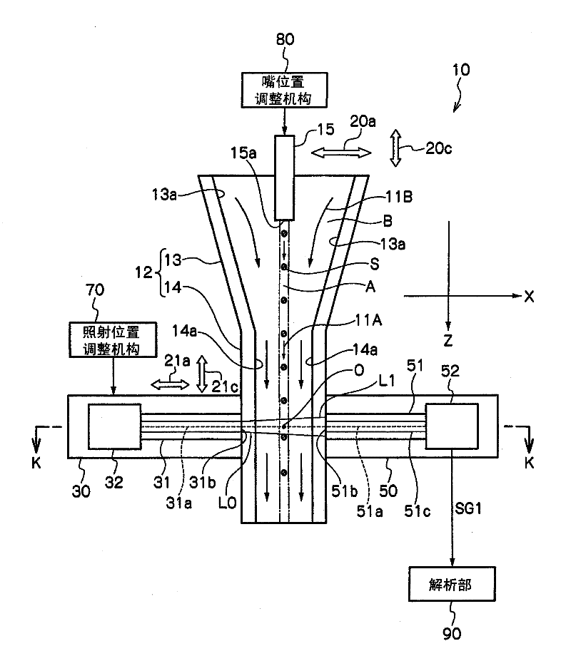
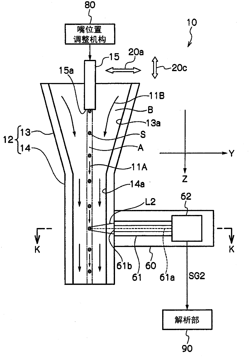
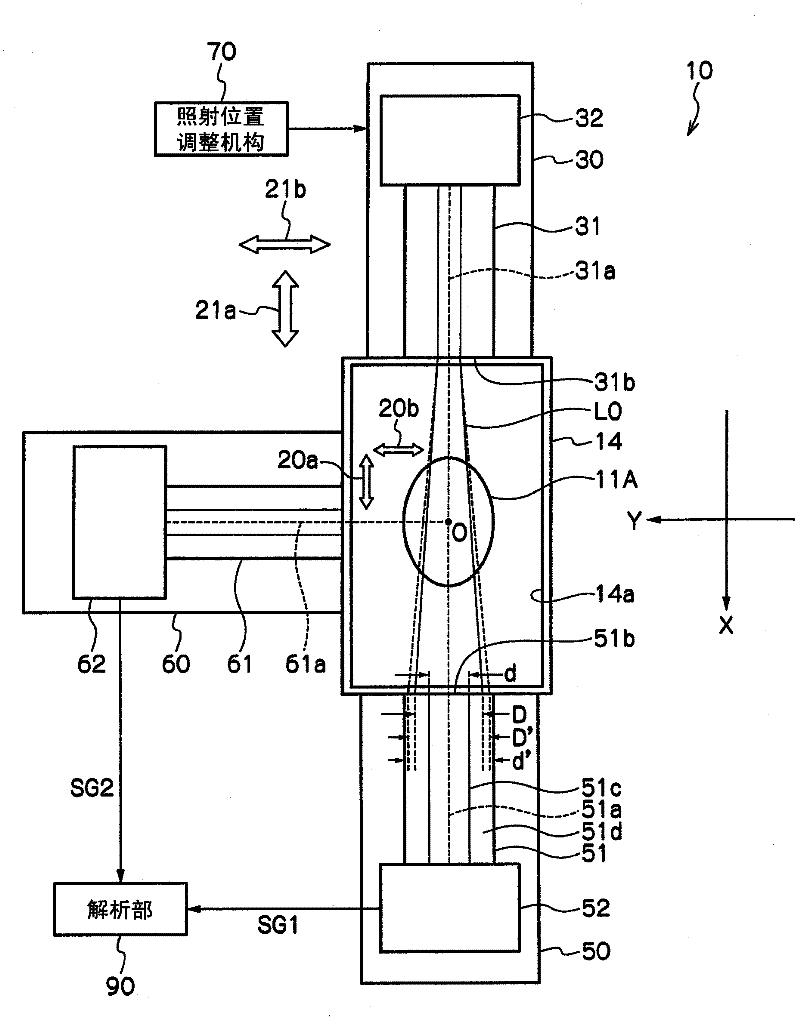
[0082] figure 1 It is a schematic longitudinal sectional view of an optical information analysis device according to an embodiment of the present invention. In addition, figure 2 Is to make figure 1 A schematic longitudinal sectional view of the optical information analysis device rotated 90 degrees around the Z axis, image 3 Yes figure 1 and figure 2 A schematic cross-sectional view of the K-K line of the optical information analysis device.

[0083] Such as Figure 1 ~ Figure 3 As shown, an optical information analysis device 10 according to an embodiment of the present invention includes: a flow channel 12 having a flow path 13a and a flow channel 14a through which liquid A flows; and a flow path from a specimen storage section (not shown) to the flow cell 12 13a introduces the introduction nozzle 15 of the liquid A; the irradiating section 30 that irradiates the sing...


PUM


Abstract

Disclosed is an optical information analysis device that enables an increase in the sensitivity to transmitted light that is received and the acquisition of consistent optical information for specimens by being provided with a light receiving unit for receiving transmitted light in a position facing an irradiation unit and by relatively adjusting the position of the flow of samples with respect to a measurement region within the flow channel. Also disclosed is an optical information analysis method. The optical information analysis device (10) is equipped with an irradiation unit (30) that irradiates a specimen (S) with irradiation light (L0), a transmitted light receiving unit (50) that receives transmitted light (L1) and detects the transmitted light as a transmitted light signal (SG1), a scattered light/fluorescence receiving unit (60) that receives side-scattered light and fluorescence (L2) and detects the side-scattered light and fluorescence as a scattered light/fluorescence signal (SG2), a nozzle position adjustment mechanism (80) that adjusts the position of the tip (15a) of an introduction nozzle (15) to match the transmitted light receiving unit (50) and the irradiation unit (30), and an analysis unit (90) that measures the optical information of the specimen (S) on the basis of the detected transmitted light signal (SG1) and scattered light/fluorescence signal (SG2) and analyzes the specimen (S).

Description

Technical field [0001] The invention relates to an optical information analysis device and an optical information analysis method. In particular, it relates to an optical information analysis device and an optical information analysis method for measuring optical information of the sample by irradiating irradiation light on a sample to be measured dispersed in a liquid flowing in a flow path. Background technique [0002] The following devices (flow position meter (flow position meter), cell sorting device) are proposed to allow a liquid containing dyed biological particles (micro objects to be tested: specimen) in the flow path The flow path of the forming member (flow channel (フロ一セル)) flows, the light irradiated from the illuminating part (irradiation part) is brought into contact with the biological particles, and the detection part (light receiving part) detects the scattered light from the biological particles And fluorescence to obtain biological information of the particl...

Claims


Application Information

Patent Timeline
Patent Type & Authority Applications(China)
IPC IPC(8): G01N15/14
CPCG01N15/1434G01N2015/1452
Inventor 月井健木村健一高桥亨徐杰
Owner 雅马拓科学株式会社
Why Eureka
Try Eureka