Optical elements, optical devices, optical detectors, optical information processing devices, optical attenuators, polarization conversion elements, projector optical systems, and optical device systems

一种光学元件、光学设备的技术,应用在光学元件、光学设备、光学检波器、光学信息处理设备、光学衰减器、偏振转换元件、投影仪光学系统和光学设备系统领域,能够解决降低光通量利用效率等问题,达到尺寸和重量减小、强度增强、自由度提高的效果

Inactive Publication Date: 2011-12-07
RICOH KK
View PDF11 Cites 11 Cited by
  • Summary
  • Abstract
  • Description
  • Claims
  • Application Information

AI Technical Summary

Problems solved by technology

As a result, the utilization efficiency of luminous flux may be reduced

Method used


Image

  • Optical elements, optical devices, optical detectors, optical information processing devices, optical attenuators, polarization conversion elements, projector optical systems, and optical device systems
  • Optical elements, optical devices, optical detectors, optical information processing devices, optical attenuators, polarization conversion elements, projector optical systems, and optical device systems
  • Optical elements, optical devices, optical detectors, optical information processing devices, optical attenuators, polarization conversion elements, projector optical systems, and optical device systems

Examples


Embodiment Construction

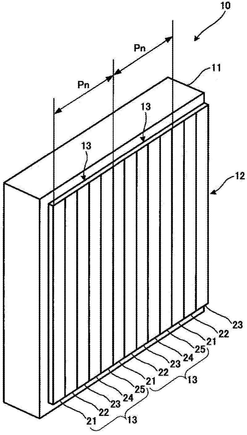
[0090] figure 1 An optical element 10 according to an embodiment of the invention is schematically shown. Such as figure 1 As shown, the optical element 10 includes a transparent substrate 11 and a diffractive structure 12 formed on the substrate 11, and serves as a diffractive element. The diffractive structure 12 includes a plurality of periodic structures 13 . exist figure 1 In , there are only two periodic structures 13 for simplicity. However, there may actually be more periodic structures 13 formed on the substrate 11 . Here, the period length (ie, width) of the periodic structure 13 is defined as a pitch “Pn”, and is equal to or greater than the wavelength of incident light to the optical element 10 .

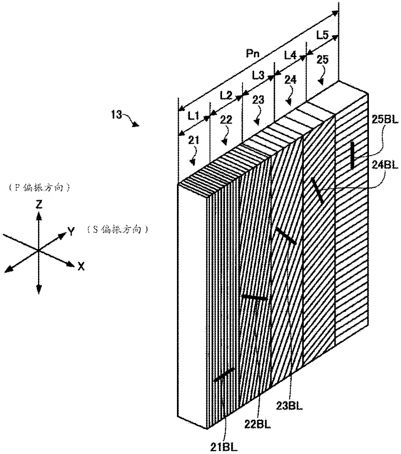
[0091] Each periodic structure 13 includes subwavelength concave-convex structures 21 , 22 , 23 , 24 and 25 . Therefore, in the diffraction structure 12, there is provided the same diffraction grating period as the pitch "Pn" of the periodic structures 13 each incl...


PUM

PropertyMeasurementUnit
wavelengthaaaaaaaaaa

Abstract

A disclosed optical element includes three or more sub-wavelength convexo-concave structures having pitches less than a wavelength of an incident light incident to the optical element and having groove depths equal to each other and a periodic structure having the three or more sub-wavelength convexo- concave structures, the pitch of the periodic structure greater than the wavelength of the incident light, in which a predetermined polarization direction of the incident light is diffracted mainly into a specific order.

Description

technical field [0001] The present invention relates to an optical element capable of diffracting light according to its polarization direction, an optical device with the optical element, an optical detector with the optical element, an optical information processing device with the optical element, and an optical attenuator with the optical element , a polarization conversion element having the optical element, a projector optical system having the optical element, the optical attenuator, and the polarization conversion element, and an optical device system comprising any one of the above. Background technique [0002] In optical detectors, optical information processing equipment, optical attenuators, polarization conversion elements, optical equipment, projector optical systems, projectors having any of the above, and various optical equipment systems having any of the above, optical An element such as a polarization separation element capable of separating the optical p...

Claims


Application Information

Patent Timeline
Patent Type & Authority Applications(China)
IPC IPC(8): G02B5/30G02B5/18G02F1/13G02F1/1335G03B21/14G11B7/135
CPCG02B5/1809G03B21/14G02F1/13362G11B7/1353G03B21/2073G02B5/18G02B5/30G02F1/1335
Inventor 平井秀明
Owner RICOH KK
Why Eureka
Try Eureka