Duplex gantry milling machine

A gantry milling machine and duplex technology, which is applied in the field of milling machines, can solve the problems that the rigidity of the gantry milling machine is greatly affected, and the ram affects the positioning accuracy of the gantry milling machine, and achieves the effects of improving the accuracy, improving the positioning accuracy and rigidity, and improving the positioning accuracy.

Active Publication Date: 2011-12-14
福建省威诺数控有限公司
View PDF7 Cites 10 Cited by
  • Summary
  • Abstract
  • Description
  • Claims
  • Application Information

AI Technical Summary

Problems solved by technology

Since the ram is hung on one side of the column, the weight of the ram will inevitably affect the positioning accuracy of the side machining of the gantry milling machine, and has a greater impact on the rigidity of the gantry milling machine

Method used


Image

  • Duplex gantry milling machine
  • Duplex gantry milling machine
  • Duplex gantry milling machine

Examples


Embodiment Construction

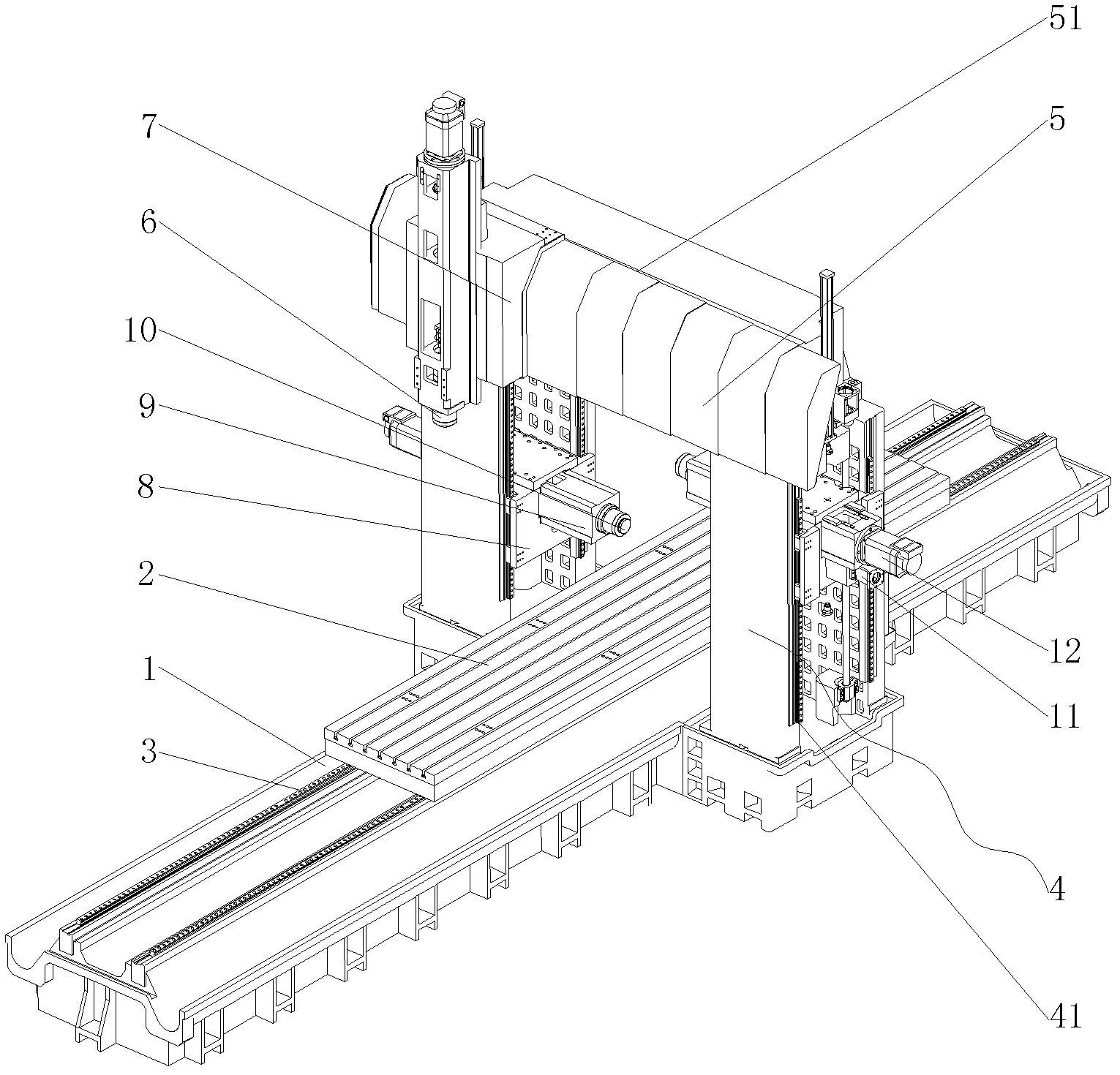
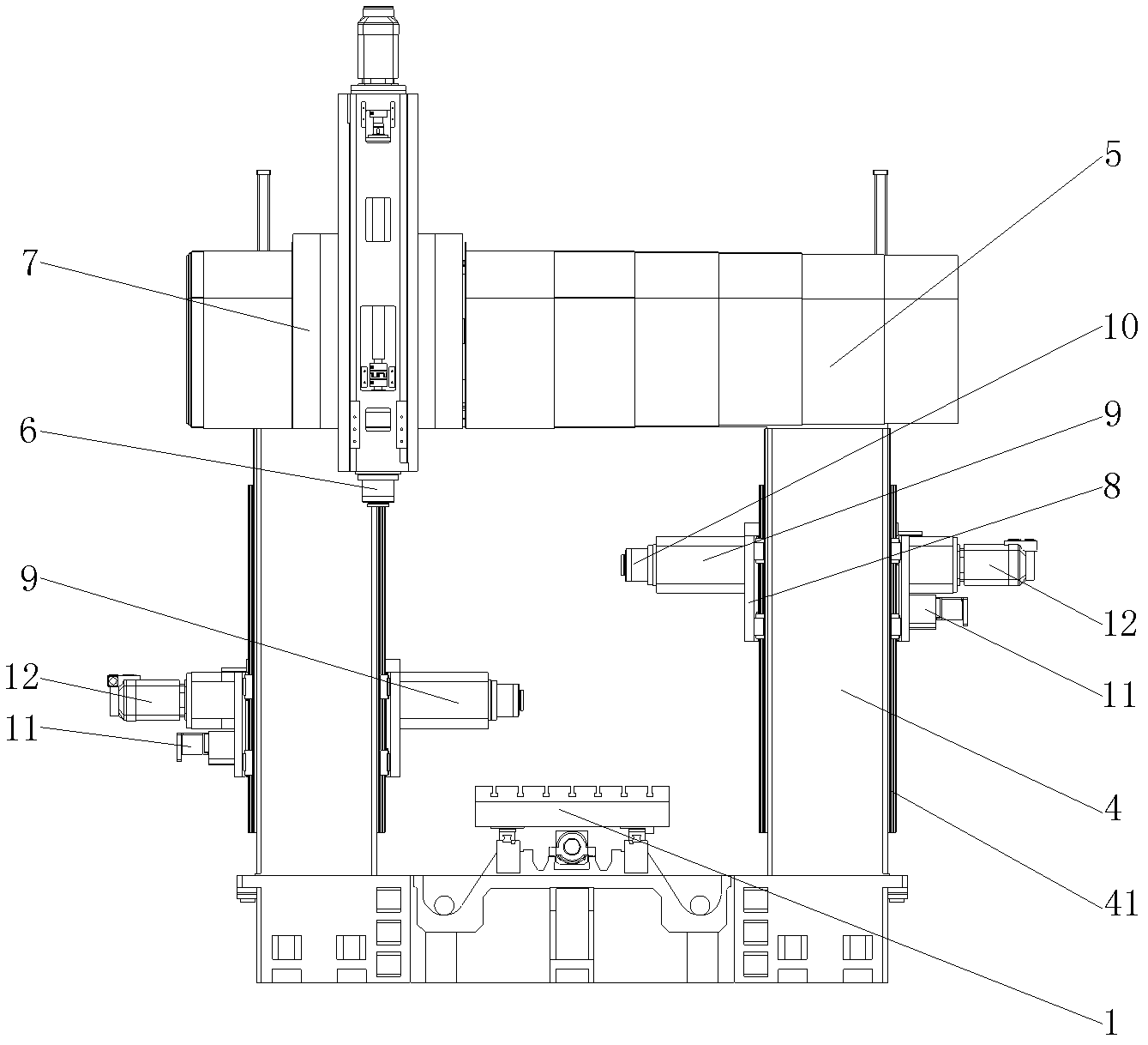
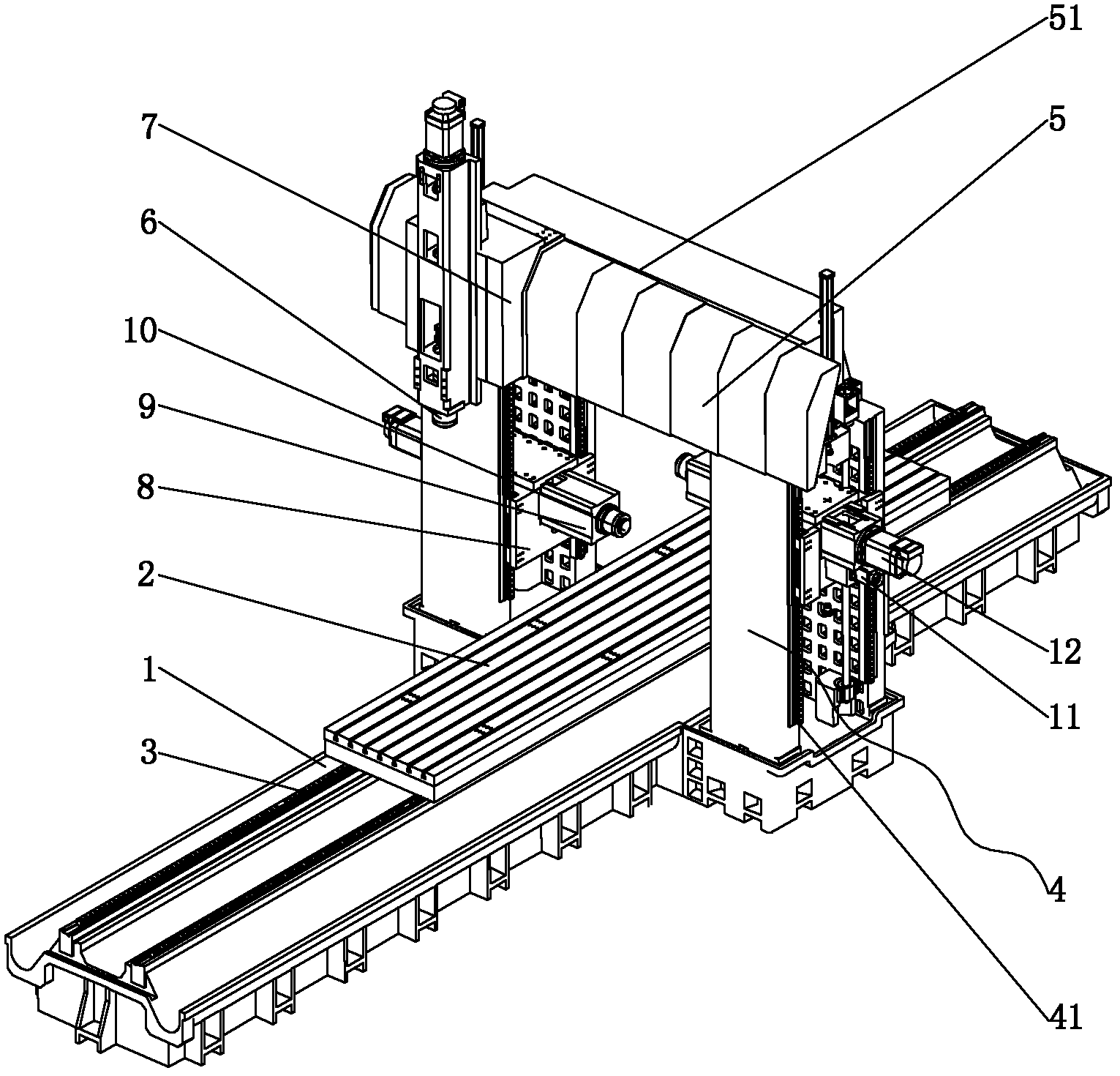
[0012] Such as figure 1 or figure 2 As shown, the present invention includes a bed 1 and a workbench 2. The bed 1 is provided with a guide rail 3. The workbench 2 is arranged on the guide rail 3 and slides along the guide rail 3. Both sides of the bed 1 are respectively provided with a frame type column structure 4. , a crossbeam frame 5 is arranged between the double columns 4, and a slide seat 7 is provided on the beam frame 5, and a longitudinally telescopic milling and boring head 6 is arranged in the slide seat 7. The column 4 is a hollow frame structure, and the two frames Both sides of the relative inner side of the side are provided with guide rails 41, and a sliding saddle 8 is provided between the two sides of the frame. Sliding up and down along the guide rail 41, a ram 9 is installed in the saddle 8, and a main shaft 10 with a horizontal milling head is arranged in the ram 9, and the ram 9 is driven by another driving mechanism 11 to drive the main shaft to move ...


PUM


Abstract

The invention discloses a compound gantry milling machine which comprises a machine body and a working table, wherein a guide rail is arranged on the machine body; the working table is arranged on the guide rail and slides along the guide rail; framework-type vertical column structures are arranged on both sides of the machine body; a cross beam frame is arranged between the two vertical columns;a sliding seat is suspended on the cross beam frame; a milling and boring head capable of stretching longitudinally is arranged in the sliding seat; the vertical columns have hollow framework-type structures; guide rails are arranged on two sides, relative to the inner side surface, of each framework; a sliding saddle is arranged between the two sides of each framework; two sides of the sliding saddle are connected with the four guide rails arranged on the two sides of each framework in a sliding way; a ram is arranged in the sliding saddle; and a main shaft with a horizontal milling head is arranged in the ram. By the compound gantry milling machine, as the four guide rails arranged on the two vertical columns are used for supporting the weight of the sliding saddles and the rams, the positioning precision, the coaxiality and the whole rigidity of lateral machining of the compound gantry milling machine are improved; meanwhile, the milling and boring head arranged on the cross beam frame can machine the upper side of the side faces of a part, so the lateral machining precision is improved.

Description

technical field [0001] The invention relates to the field of milling machines, in particular to the structure of a compound gantry milling machine. Background technique [0002] The bed both sides of existing gantry milling machine form portal frame by column and beam frame, and beam frame can do lifting motion along the guide rail on the column of both sides. There are 1 to 2 milling heads with vertical spindles on the beam frame, and the milling heads can move laterally along the guide rail of the beam frame. A ram is hung on one side of the column on both sides, and a milling head with a horizontal spindle is installed in the ram, and the ram drives the milling head to move up and down along the guide rail of the column. Since the ram is hung on one side of the column, the self-weight of the ram will inevitably affect the positioning accuracy of the side machining of the gantry milling machine, and has a greater impact on the rigidity of the gantry milling machine. Con...

Claims


Application Information

Patent Timeline
Patent Type & Authority Applications(China)
IPC IPC(8): B23Q1/01B23P23/02
CPCB23Q1/017B23Q1/012B23Q1/015B23Q39/026
Inventor 翁强
Owner 福建省威诺数控有限公司
Why Eureka
Try Eureka