A laying method and auxiliary device for laying glass fiber cloth at the root of wind power blades

A technology for wind power blades and auxiliary devices, which is applied to other household appliances, household appliances, household components, etc., can solve problems such as inability to meet large-scale production, unfavorable blade production efficiency, and unfavorable large-scale production.

Inactive Publication Date: 2011-12-14
TIANJIN CRRC WIND POWER BLADE ENG CO LTD
View PDF4 Cites 7 Cited by
  • Summary
  • Abstract
  • Description
  • Claims
  • Application Information

AI Technical Summary

Problems solved by technology

The main materials for making blades are glass fiber cloth and infusion resin. The amount of glass fiber cloth used in megawatt-level blades is very large. There can be more than 100 layers of glass fiber cloth at the root of the blade, and so many layers of glass fiber cloth It takes a long time to rely on the operator to lay layer by layer on the blade mold, which is not conducive to mass production. Therefore, the first disadvantage of laying glass fiber cloth directly manually is that it takes too long to occupy the mold, which is not conducive to large-scale production. Improving the production efficiency of blades cannot meet the needs of large-scale production
[0003] The second disadvantage of directly laying glass fiber cloth manually: the pre-cut glass fiber cloth is easy to form creases when folded and stored, and it is easy to cause bulges and wrinkles when laying, reducing the strength and performance of the blade
[0004] The third disadvantage of directly laying glass fiber cloth manually: due to the large arc of the blade root of the megawatt-level blade mold, when the glass fiber cloth is laid, the two ends of the glass fiber cloth are easy to slide down, resulting in the root of the glass fiber cloth. The thickness is uneven, and the uneven thickness of the blade root will have a certain impact on the subsequent blade drilling and bolt installation.

Method used


Image

  • A laying method and auxiliary device for laying glass fiber cloth at the root of wind power blades
  • A laying method and auxiliary device for laying glass fiber cloth at the root of wind power blades
  • A laying method and auxiliary device for laying glass fiber cloth at the root of wind power blades

Examples


Embodiment Construction

[0015] The present invention will be further described in detail below in conjunction with the accompanying drawings and specific embodiments.

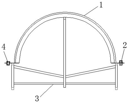
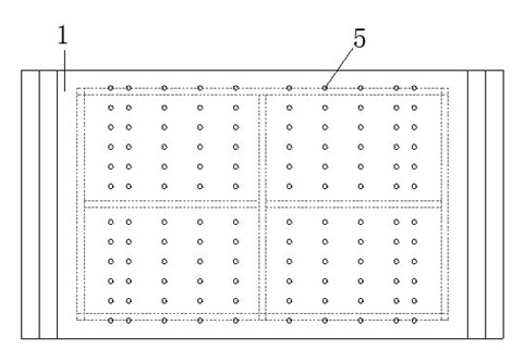
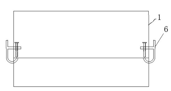
[0016] by attaching Figure 1-4 It can be seen that the present invention relates to a method for laying glass fiber cloth at the root of wind power blades. First, a fixing bracket is fixed, and then the semicircular steel plate profile is installed on the fixing bracket, and the glass fiber cloth fixing groove is installed on the At both ends of the semicircular steel plate surface, fully unfold the glass fiber cloth to be laid, and cover it on the semicircular steel plate surface, and at least ensure that the two ends of the first and last two layers of glass fiber cloth exceed the glass fiber cloth fixing groove, When the glass fiber cloth fixing square steel is pressed on the glass fiber cloth fixing groove, the glass fiber cloth can be pressed down, and then the glass fiber cloth fixing square steel is pressed on the glass fiber ...


PUM

PropertyMeasurementUnit
thicknessaaaaaaaaaa

Abstract

The invention provides a laying method and auxiliary device for laying glass fiber cloth at the root of wind power blades. Above, the two ends of the semi-circular steel plate are fixed grooves for glass fiber cloth, and the fixed grooves for glass fiber cloth are equipped with fixed square steel, and there are process holes on the semi-circular steel plate. Then lay glass fiber cloth on the device according to the order of leaf root laying, and fix it after laying a certain number of layers of glass fiber cloth. After all the glass fiber cloth is laid, directly lift the device and put it in the shell. The steel frame can still be used for the laying of the next set of glass fibers. The device is simple in use, convenient in process operation, good in laying quality of glass fiber cloth, and fast in hoisting time; simple in manufacture, convenient in assembly, low in cost, and long in service life.

Description

technical field [0001] The invention relates to an auxiliary device for laying glass fiber cloth in the manufacturing process of large composite material blades, in particular to a laying method and auxiliary device for laying glass fiber cloth at the root of a wind power blade. Background technique [0002] In wind power equipment, the blade of the wind turbine is an important key component, and its performance directly affects the power generation of the generator set. The main materials for making blades are glass fiber cloth and infusion resin. The amount of glass fiber cloth used in megawatt-level blades is very large. There can be more than 100 layers of glass fiber cloth at the root of the blade, and so many layers of glass fiber cloth It takes a long time to rely on the operator to lay layer by layer on the blade mold, which is not conducive to mass production. Therefore, the first disadvantage of laying glass fiber cloth directly manually is that it takes too long t...

Claims


Application Information

Patent Timeline
Patent Type & Authority Applications(China)
IPC IPC(8): B29C70/34B29L31/08
Inventor 梁自禄陈煌路忠林王学花张洪涛
Owner TIANJIN CRRC WIND POWER BLADE ENG CO LTD
Why Eureka
Try Eureka