Eureka AIR delivers breakthrough ideas for toughest innovation challenges, trusted by R&D personnel around the world.

Primary Air Distribution Method for Circulating Fluidized Bed Boiler

A circulating fluidized bed and boiler technology, which is applied in the directions of fluidized bed combustion equipment, combustion methods, and fuels burned in a molten state, can solve problems such as poor economy, reduced power supply efficiency, and increased plant power consumption. The effect of optimizing the combustion state of the furnace, improving the fluidization of materials, and reducing the power consumption rate of the plant

Inactive Publication Date: 2011-12-14
INST OF ENGINEERING THERMOPHYSICS - CHINESE ACAD OF SCI
View PDF10 Cites 8 Cited by
  • Summary
  • Abstract
  • Description
  • Claims
  • Application Information

AI Technical Summary

Problems solved by technology

However, it is followed by the increase of plant power consumption rate and the decrease of power supply efficiency, and the economy is not good.

Method used


Image

  • Primary Air Distribution Method for Circulating Fluidized Bed Boiler
  • Primary Air Distribution Method for Circulating Fluidized Bed Boiler
  • Primary Air Distribution Method for Circulating Fluidized Bed Boiler

Examples


Embodiment 1

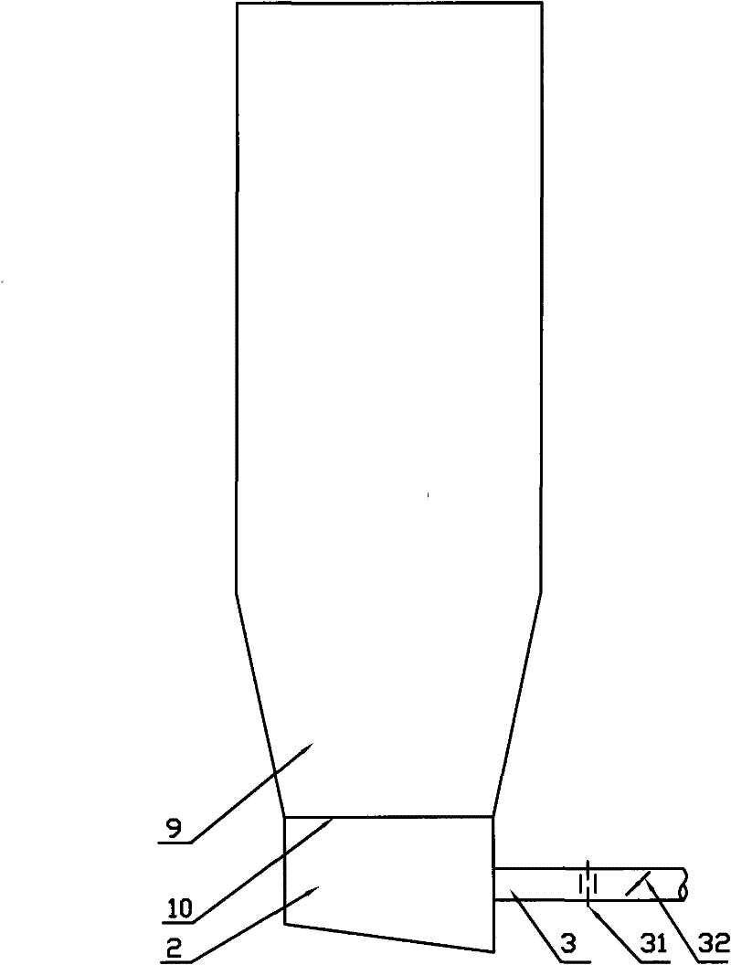
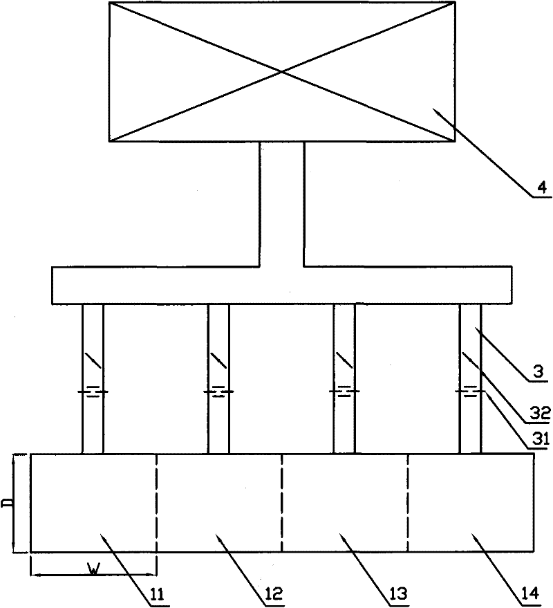
[0020] figure 1 and figure 2 It is a top view diagram of a 670t / h circulating fluidized bed boiler in Example 1 of the present invention. The bottom of the furnace 9 is provided with an air distribution plate 10 with a width of 22.7 meters and a depth of 4.5 meters. The air distribution plate 10 is divided into successive phases along the width direction. The four adjacent air distribution panel partitions 11, 12, 13, and 14, and each air distribution panel partition is provided with an air chamber ( figure 1 The label 2 in represents these 4 air chambers), each air chamber is not connected to each other; each air chamber is connected with the air preheater 4 of the boiler through the air pipe 3, when the air pipe 3 is drawn out from the air preheater 4 It is a main pipe, which is divided into 4 branch pipes before passing into each air chamber, and each branch pipe is equipped with an air flow measuring device 31 and a regulating device 32 . The branch pipes of the air duc...

Embodiment 2

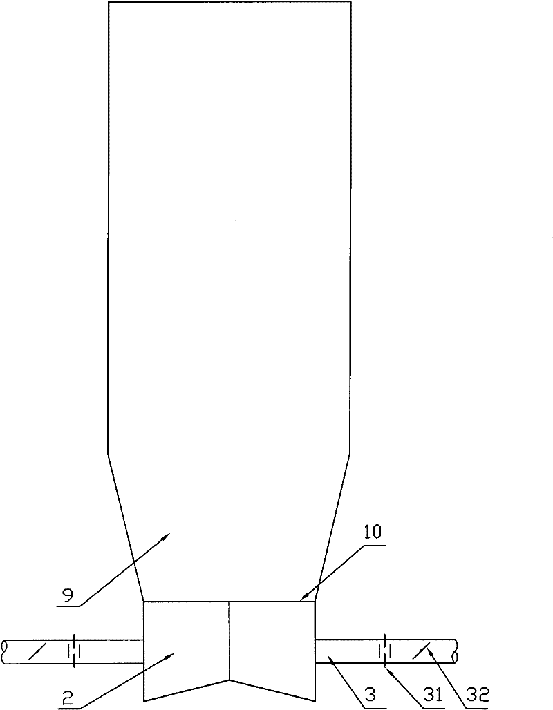
[0024] image 3 and Figure 4 It is a schematic diagram of a 600MW circulating fluidized bed boiler in Example 2 of the present invention. The boiler has a single furnace and a single air distribution plate. The bottom of the hearth 9 is provided with an air distribution plate 10 of 32 meters x 6.6 meters. Close to the air preheater 4 is the rear wall of the furnace, and opposite to it is the front wall of the furnace. Standing in front of the furnace faces the boiler, the left side is the left side wall, and the right side is the right side side wall.

[0025] Divide the air distribution board 10 into 2 rows, 4 in each row, a total of 8 air distribution board partitions (11-18), each air distribution board partition is provided with an equal pressure air chamber ( image 3 The middle mark 2 represents these 8 air chambers), and each air chamber is not connected to each other.

[0026] Each air chamber 2 is connected to the air preheater 4 of the boiler through the air pipe...


PUM


Abstract

The invention discloses a method for distributing primary air of a circulating fluidized bed boiler, and relates to the technology of a circulating fluidized bed boiler. There is an air chamber at the bottom, and the air chambers are not connected to each other; each air chamber is connected to the air preheater of the boiler through an air pipe; each air pipe is equipped with an air flow measuring device and an adjustment device. device; when the boiler is running, adjust the air flow regulating device to control the primary air volume flowing into each air chamber. The method of the invention can improve the uniformity of the primary air distribution of the circulating fluidized bed boiler, especially the large capacity circulating fluidized bed boiler.

Description

technical field [0001] The invention relates to the technical field of circulating fluidized bed boilers, in particular to a primary air distribution method for circulating fluidized bed boilers. technical background [0002] The conventional circulating fluidized bed primary air distribution method is to install an air distribution plate with a hood at the bottom of the furnace, and a single air chamber connected to the entire air distribution plate is installed under the air distribution plate; for the more special underpants tubular furnace, That is to say, the furnace type with single hearth and double air distribution panels is that two independent furnace air distribution panels are equipped with independent air chambers. The air duct leads the primary air from the air preheater into the air chamber. The air duct usually enters the air chamber from the rear wall or side walls. The air chamber is usually designed with an equal pressure air chamber, with an inclined fl...

Claims


Application Information

Patent Timeline
Patent Type & Authority Applications(China)
IPC IPC(8): F23C10/20
Inventor 吕清刚高鸣孙运凯宋国良
Owner INST OF ENGINEERING THERMOPHYSICS - CHINESE ACAD OF SCI
Why Eureka
Eureka Blog
Learn More