Rod position detection system in nuclear power plant and its free-fall time testing method

A detection system and technology for nuclear power plants, which are applied to the rod position detection system of nuclear power plants and the field of free-drop rod time testing, can solve the problems of difficult rod-drop testing, difficulty in ensuring the consistency of multiple rod bundles, etc. time, ease of testing, and improved reliability

Active Publication Date: 2011-12-14
STATE NUCLEAR POWER AUTOMATION SYST ENGCO
View PDF8 Cites 15 Cited by
  • Summary
  • Abstract
  • Description
  • Claims
  • Application Information

AI Technical Summary

Problems solved by technology

The test of the free fall time of the control rod requires a relay to short-circuit the primary of the transformer when the power supply is cut off, such as short-circuiting the relay contact 52 of the primary stage of the transformer T1, and at the same time short-circuiting the secondary of the transformer, and then by detecting the public transmission The change of the voltage on the cable 42 obtains the rod drop time curve, and the resistance R4 on the common wire 42 is very small and it is difficult to ensure the consistency of multiple rod bundles, and it is difficult to realize the rod drop test of the emergency shutdown during the reactor operation, so , it is necessary to further improve the nuclear power plant rod position detection system and its free fall time test method to make the test more convenient and reliable

Method used


Image

  • Rod position detection system in nuclear power plant and its free-fall time testing method
  • Rod position detection system in nuclear power plant and its free-fall time testing method
  • Rod position detection system in nuclear power plant and its free-fall time testing method

Examples


Embodiment Construction

[0023] The present invention will be further described below in conjunction with the accompanying drawings and embodiments.

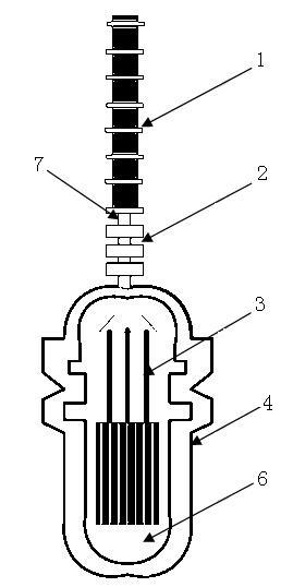
[0024] Figure 5 It is a schematic diagram of the detection coil structure in the rod position detection system of the present invention.

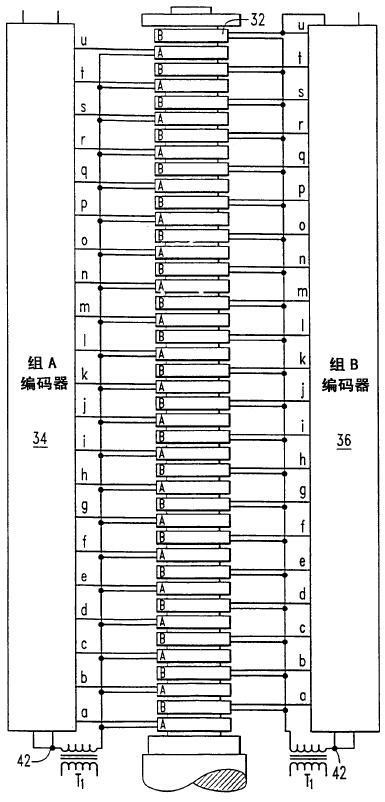
[0025] See figure 1 and Figure 5 , the rod position detection system of the present invention comprises a position detection device 1 and a control rod group 3 arranged in the pressure vessel 4, the position detection device 1 is installed outside the travel casing 7, and the position detection device 1 and the control rod drive Mechanism 2 is connected, and the control rod drive mechanism includes claw parts, yoke coil assemblies, pressure bearing parts and drive rod parts, and the drive rod parts are connected to control rod group 3, wherein the position detection device 1 includes multiple A continuous control unit, the control unit is divided into two groups of A and B alternately, each control unit includes...


PUM


Abstract

The invention discloses a rod position detecting system of a nuclear power plant and a method for testing free rod-drop time thereof. The detecting system comprises a position detecting device and a control rod set arranged in a pressure container; the position detecting device is installed outside a travel housing; the position detecting device is connected with the control rod set through a control rod driving mechanism, wherein the position detecting device comprises a plurality of continuous control units; each control unit comprises a sensor coil and a rod drop testing coil; a plurality of the sensor coils are powered by a transformer T1; the rod drop testing coils of each control unit are connected end to end to form two leading-out terminals for testing induction voltage. According to the rod position detecting system of the nuclear power plant and the method for testing free rod-drop time thereof provided by the invention, a curve of rod drop time is obtained by arranging the rod drop testing coil and using the voltage induced in the rod drop testing coil during the rapid drop course of the control rod; and the free rod-drop time can be tested conveniently and the testing reliability is further improved.

Description

technical field [0001] The invention relates to a control rod detection system and its free-fall time testing method, in particular to a nuclear power plant rod position detection system and its free-fall time testing method. Background technique [0002] The rod position detection system of the nuclear power plant uses the control rod position detection device and applies the principle of coil induction to display the position of the control rod in the core. When the power is cut off, the control rod assembly quickly falls into the core by its own weight to realize the shutdown of the reactor. At this time, relying on the voltage induced in the coil of the control rod position detection device during the rapid descent of the control rod, the rod drop time curve is obtained. [0003] In the nuclear reactor of the pressurized water reactor nuclear power plant, the control rod assembly is in a high temperature and high pressure pressure vessel. The position of the control rod ...

Claims


Application Information

Patent Timeline
Patent Type & Authority Applications(China)
IPC IPC(8): G21C17/10G21C17/00
CPCG21C7/12G21C7/36Y02E30/39G21C17/10Y02E30/30
Inventor 刘爱青唐崟张斌王冠峰华明俊
Owner STATE NUCLEAR POWER AUTOMATION SYST ENGCO
Why Eureka
Try Eureka