A switching power supply output short circuit protection circuit

A switching power supply, output short circuit technology, used in emergency protection circuit devices, protection against overcurrent, electrical components, etc., can solve problems such as large forward voltage drop deviation, failure to work normally, and unstable supply, Achieve the effect of simple circuit debugging, no debugging, and quick startup.

Inactive Publication Date: 2011-12-14
MORNSUN GUANGZHOU SCI & TECH
View PDF3 Cites 27 Cited by
  • Summary
  • Abstract
  • Description
  • Claims
  • Application Information

AI Technical Summary

Problems solved by technology

[0010] (2) When a fault occurs until it enters the protection stage
Diodes work under low current, and the deviation of forward voltage drop is very large, and the consistency of voltage drop formed after series connection is poor. During mass production, each product needs to be individually debugged, which is extremely inconvenient
[0043] 1. It is difficult to debug the circuit. Capacitor C1 is the shared capacitor of the start-up time delay circuit and the protection time-length timing circuit. The values ​​of resistor R1 and resistor R2 are therefore very different. If the resistor R1 is small, the op amp will work at an unreasonable bias state
It cannot work normally without changing the number of diodes in series
[0044] 2. When the resistance R1 is 1 hour, and the diode D1 is changed to multiple diodes in series, since the voltage drop of the diodes connected in series has a large deviation due to the low current operation, when the circuit is mass-produced, each product must be debugged, which is extremely inconvenient
[0045] 3. When the resistance R1 is large, the input bias voltage of the operational amplifier can be reduced, but at this time, the protection circuit starts slowly and the reliability decreases
[0046] 4. When changing the capacitor C1, when adjusting the hiccup time of the circuit, it will have a great influence on the selection of the resistor R1, and it is difficult to debug the circuit
[0047] 5. The op amp is replaced by an NPN tube as a differential input stage, but there are very few types of this op amp, the price is more than ten times higher than that of ordinary op amps, and the supply is unstable

Method used


Image

  • A switching power supply output short circuit protection circuit
  • A switching power supply output short circuit protection circuit
  • A switching power supply output short circuit protection circuit

Examples


Embodiment 1

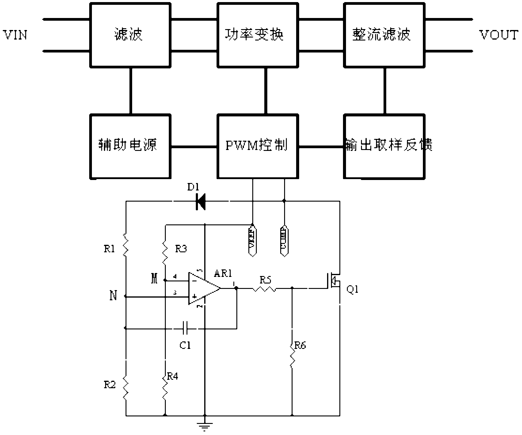
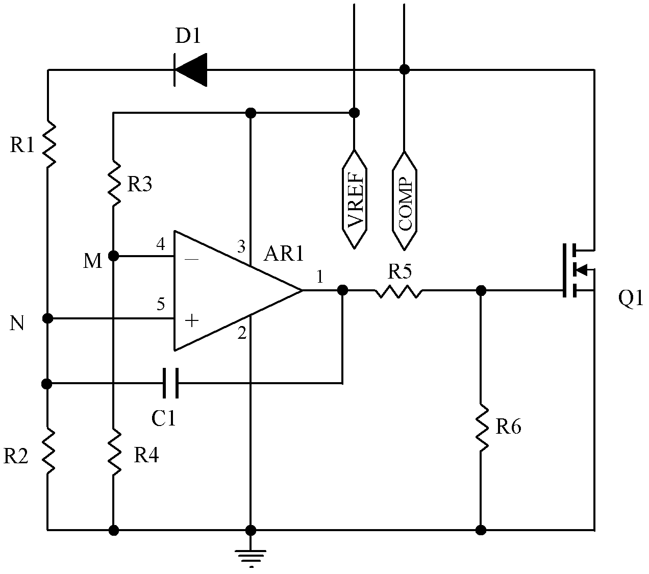
[0081] see Figure 9 , including: a power input port V REF , a ground port, a control port COMP, a first resistor R1, a second resistor R2, a third resistor R3, a fourth resistor R4, a fifth resistor R5, a first capacitor C1, a second Capacitor C2, a crystal diode D1, an N-channel FET Q1, and an operational amplifier AR1. Power input port V REF Connect to pin 7 of the power supply terminal of the op amp, V REF Also connected to the fourth resistor R4 through the third resistor R3 and connected to the ground port through the resistor R4; the control port COMP is connected to the drain of the field effect transistor Q1, and the control port COMP is also connected to the second resistor R2 through the first resistor R1 And connected to the ground port through the resistor R2; the inverting input terminal 2 of the operational amplifier AR1 is connected to the connection point of the third resistor R3 and the fourth resistor R4, and the non-inverting input terminal 3 of the oper...

Embodiment 2

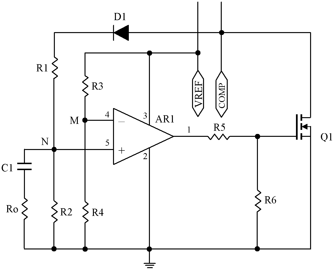
[0095] see Figure 10 , including: a power input port V REF , a ground port, a control port COMP, a first resistor R1, a second resistor R2, a third resistor R3, a fourth resistor R4, a fifth resistor R5, a sixth resistor R6, a first Capacitor C1, a second capacitor C2, a crystal diode D1, a crystal transistor Q1, and an operational amplifier AR1. Transistor Q1 is NPN type, preferably high multiple such as S9014, V REF Connect to the power supply terminal 7 of the operational amplifier AR1, V REF It is also connected to the resistor R4 through the resistor R3 and connected to the ground terminal through the resistor R4; COMP is connected to the collector of the transistor Q1, and COMP is also connected to the resistor R2 through the resistor R1 and connected to the ground terminal through the resistor R2; the operational amplifier AR1 is reversed The phase input terminal 2 is connected to the connection point of the resistor R3 and the resistor R4, the non-inverting input t...

Embodiment 3

[0099] see Figure 11 , which is a lower cost solution, including: a power input port V REF , a ground port, a control port COMP, a first resistor R1, a second resistor R2, a third resistor R3, a fourth resistor R4, a fifth resistor R5, a sixth resistor R6, a seventh resistor Resistor R7, a first capacitor C1, a second capacitor C2, NPN transistor Q1, PNP transistor Q2, NPN transistor Q3; V REF Connect the emitter of the transistor Q2 and one end of the resistor R4, the other end of the resistor R4 is connected to the base of the transistor Q2, and the base of the transistor Q2 is also connected to the collector of the transistor Q3 through the resistor R3; the control port COMP is connected to the terminal of the transistor Q1 The collector, the control port COMP is also connected to the resistor R2 through the resistor R1 and connected to the ground terminal through the resistor R2; the capacitor C1 and the resistor R2 are connected in parallel; the base of the transistor Q...


PUM


Abstract

The invention discloses a switching power supply output short-circuit protection circuit, which includes a control port, a start-up time delay circuit, a voltage detection circuit, a protection duration timing circuit, and a switching transistor. When the switching power supply has an output short circuit or overcurrent , when the voltage at the control port exceeds the set high level or above, after the start-up time delay circuit, the voltage detection circuit outputs a high level to charge the protection duration timing circuit At the same time, the switching transistor is turned on, the control port is pulled to a low level, and the switching power supply stops working. The switching power supply output short circuit protection circuit of the present invention is easy to debug, and each parameter can be adjusted independently during debugging. Once confirmed, it can realize free debugging during mass production, and also realize that when the output of the switching power supply is over-current or short-circuited, the circuit starts quickly, and the switching power supply enters the hiccup protection working mode.

Description

technical field [0001] The invention relates to a switching power supply protection circuit, in particular to a switching power supply output short circuit and overcurrent protection circuit. Background technique [0002] Switching power supply is a kind of power supply that uses modern power electronics technology to control the time ratio of switching on and off to maintain a stable output voltage. Switching power supply is generally controlled by pulse width modulation (PWM) Integrated circuit (IC) and power insulation gate field effect transistor (MOSFET). [0003] Switching power supplies have been developing in the direction of high efficiency, high power density, high reliability, and complete protection functions. Among them, high reliability is mainly reflected in the service life, output overcurrent, and output short circuit protection functions. Most of the current popular protection circuits are Double optocoupler feedback circuit to achieve a more ideal protect...

Claims


Application Information

Patent Timeline
Patent Type & Authority Applications(China)
IPC IPC(8): H02H7/10H02H3/08
Inventor 王保均
Owner MORNSUN GUANGZHOU SCI & TECH
Why Eureka
Try Eureka