racetrack memory device

A storage device and device technology, applied in the field of memory storage systems

Active Publication Date: 2011-12-14
GLOBALFOUNDRIES INC
View PDF6 Cites 4 Cited by
  • Summary
  • Abstract
  • Description
  • Claims
  • Application Information

AI Technical Summary

Problems solved by technology

[0003] Therefore, prior art racetrack memory technologies favor long runway

Method used


Image

  • racetrack memory device
  • racetrack memory device
  • racetrack memory device

Examples


Embodiment Construction

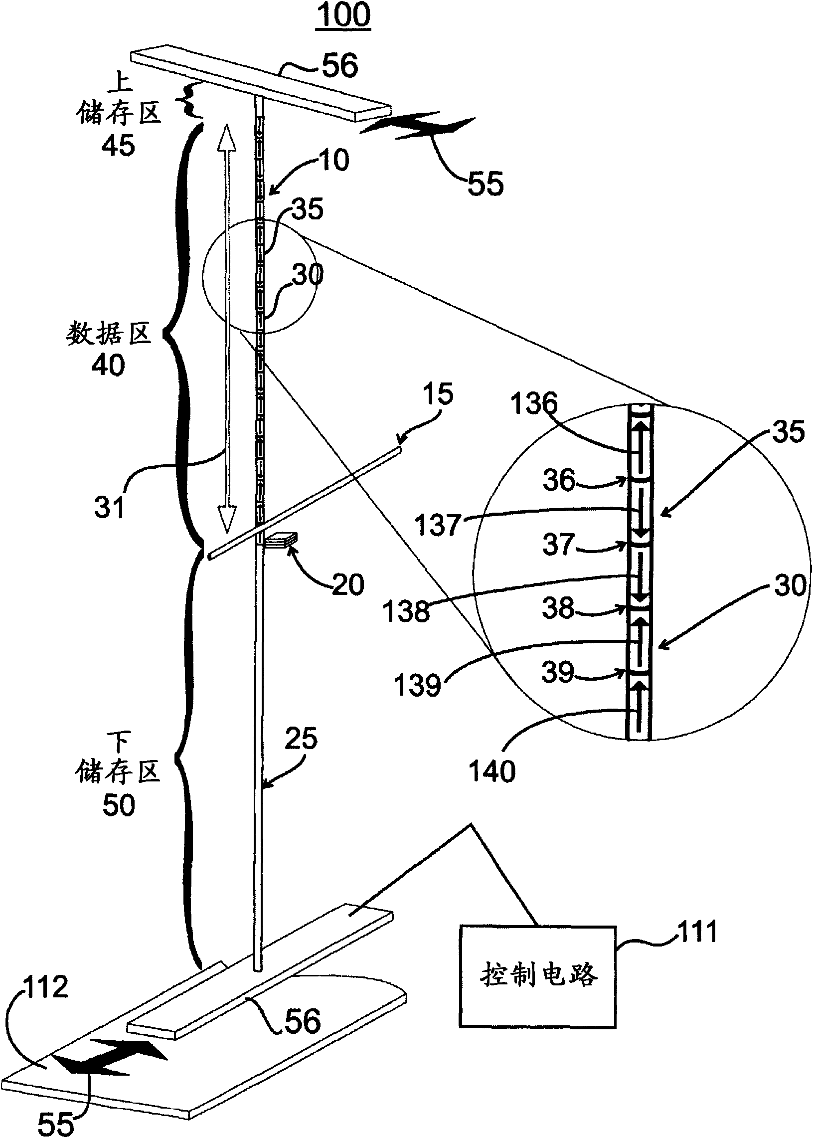
[0012] figure 1 An exemplary magnetic memory system 100 is shown comprising a magnetic shift register 10 employing a write element 15 and a read element 20 . Both the read element 20 and the write element 15 form the read / write element of the system 100 . The magnetic shift register 10 includes a data column 25 comprising thin wires (or tracks) preferably made of ferrimagnetic or ferromagnetic material. The data column 25 can be magnetized in one direction or the other within a small area using the write element 15 .

[0013] The order parameter (ie, magnetization direction or magnetic momentum direction) of the magnetic material from which the track is made can generally change from one direction to another between domains. This change in the direction of the magnetic momentum forms the basis for storing information in the data column 25 . Depending on the desired encoding scheme of the shift register, data can be stored in 1) the magnetized regions (e.g. magnetic domains)...


PUM


Abstract

A racetrack memory storage device moves domain walls along the racetrack in one direction only. The reading element can be positioned at one end of the racetrack (rather than in the middle of the racetrack). The domain walls are annihilated upon moving them across the reading element but their corresponding information is read into one or more memory devices (e.g., built-in CMOS circuits). The information can then be processed in circuits for computational needs and written back into the racetrack either in its original form (as it was read out of the racetrack) or in a different form after some computation, using a writing element positioned at the end of the racetrack opposite to the reading element. Such a racetrack can be built more simply and has greater reliability of operation than previous racetrack memory devices.

Description

technical field [0001] The present invention relates to memory storage systems and, in particular, to a method of using electric currents to move magnetic domain walls across read and write devices, thereby allowing data to be stored in and from domains within magnetic raceways Or domain wall readout memory storage system for data. Background technique [0002] Racetrack memory devices store information in the form of magnetic domain walls in magnetic nanowires, or "racetracks." The domain walls are moved backwards and forwards along the nanowire using short (nanosecond) pulses of current, in which the electrons carrying the current are spin-polarized. The spin-polarized current carries spin angular momentum, which is transferred to the domain wall, causing the domain wall to move in the direction of electron flow. For example, a series of domain walls (representing 0s and 1s) can be reciprocated along the racetrack with a read device and a write device placed in the middl...

Claims


Application Information

Patent Timeline
Patent Type & Authority Applications(China)
IPC IPC(8): G11C19/08
CPCG11C19/0841G11C19/0808G11C11/14Y10S977/933
Inventor S·帕金
Owner GLOBALFOUNDRIES INC
Why Eureka
Try Eureka