
A grinding method of high-precision permanent magnet seat

A permanent magnet and high-precision technology, applied in the field of grinding, can solve the problems of poor precision and difficult measurement, and achieve the effects of simplifying alignment and measuring times, good consistency, and improving processing efficiency and processing quality

Inactive Publication Date: 2011-12-21
FLIGHT AUTOMATIC CONTROL RES INST
View PDF4 Cites 3 Cited by
  • Summary
  • Abstract
  • Description
  • Claims
  • Application Information

AI Technical Summary

Problems solved by technology

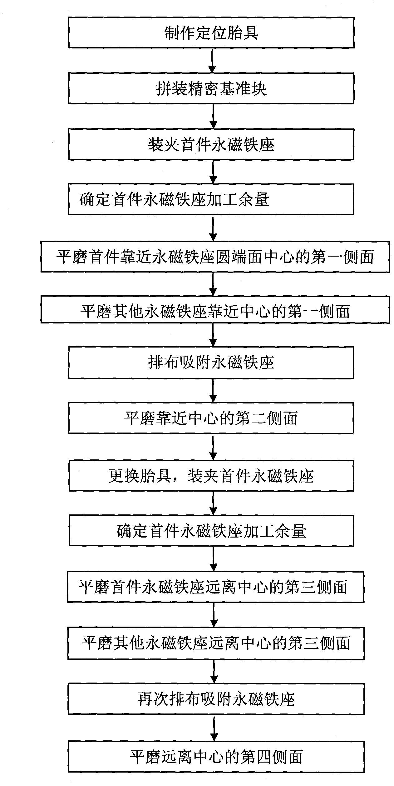
[0004] The purpose of the present invention is: in order to solve the problems of repeated clamping and positioning, difficult measurement and poor precision in the processing of the accelerometer permanent magnet base parts in the prior art; solve the problem of magnetic weakening caused by high cutting heat generated during cutting; Two sets of flatness and perpendicularity requirements and the magnetic function requirements of the parts, the invention provides a method that can effectively locate and install accelerometer permanent magnet seat parts in flat grinding processing, while ensuring perpendicularity, symmetry and high dimensional accuracy Requirements, reduce repeated clamping positioning and measurement methods in processing, and propose suitable grinding parameters for such materials

Method used


Image

  • A grinding method of high-precision permanent magnet seat
  • A grinding method of high-precision permanent magnet seat
  • A grinding method of high-precision permanent magnet seat

Examples


Embodiment Construction

[0059] The present invention will be further described below in conjunction with the accompanying drawings and through specific embodiments.

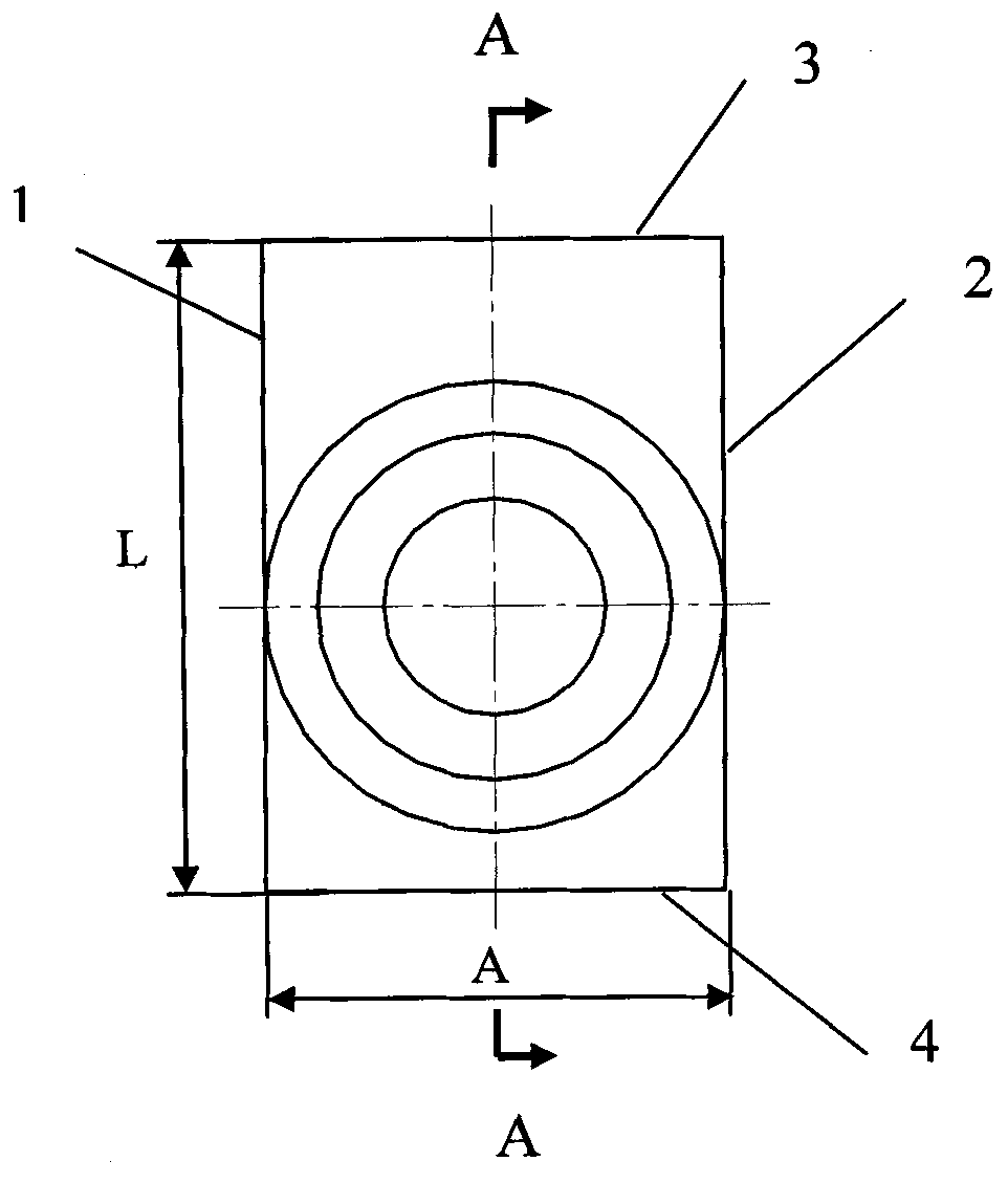
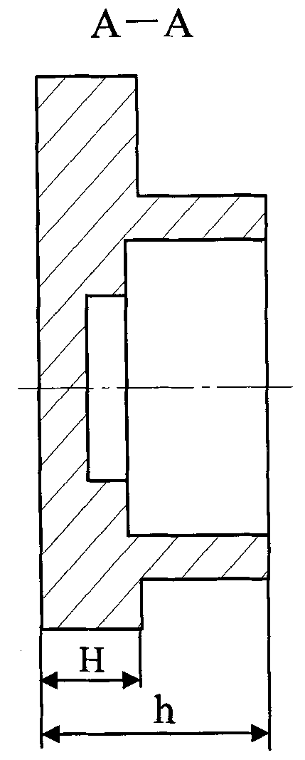
[0060] see figure 2 and image 3 , figure 2 It is a front view of a certain accelerometer permanent magnet seat part in a preferred embodiment of the processing method of the accelerometer permanent magnet seat part of the present invention, image 3 yes figure 2 left view of . In this embodiment, one end of the part is a circular platform, and the other end is a square platform. part size, height Director Fang width Thickness H=3.8mm, and the perpendicularity between the first side 1 and the third side 3 of the square platform is required to be φ0.02, the reference plane of the third side 3 and the center of the circular platform are 8.5±0.01mm, the reference of the first side 1 and the circular platform The center size is 6.75mm. In order to ensure the size and position accuracy required by these designs, it is necessary...


PUM

PropertyMeasurementUnit
Verticalityaaaaaaaaaa
Flatnessaaaaaaaaaa

Abstract

The invention belongs to a processing technology for a precision component made of special material, and relates to a processing method for high-precision benchmark conversion of parts made of soft magnetic alloy. An auxiliary positioning tool is arranged, and the problem of mutual verticality of a plurality of surfaces can be solved; a high-precision benchmark block is matched for conversion of measurement benchmarks, and the problem that actual processing dimensions cannot be determined easily can be solved; the tool is adopted for conversion of the processing benchmarks, a processing supply terminal is arranged, and the defects that each part needs to be centered and measured each time when being processed can be overcome; and moreover, magnetic weakening can be avoided through optimizing processing parameters and selecting reasonable sand wheels and cooling methods. Compared with the conventional processing method, the problems of the traditional method that the parts cannot be clamped and positioned easily and need to be clamped and centered multiple times during processing can be solved; high position accuracy and dimensional accuracy of side faces can be guaranteed at the same time; and the processing efficiency can be increased greatly, good dimensional consistency can be maintained, and the processing quality can be stabilized.

Description

technical field [0001] The invention relates to a grinding method, in particular to a grinding method of a soft magnetic alloy high-precision permanent magnet seat. Background technique [0002] The material of the permanent magnet base of an accelerometer is 1J50 soft magnetic alloy. The size and position accuracy of the parts are required to be high, and the verticality, flatness and parallelism of the planes on it must be guaranteed at the same time. Since the part has a round and square structure, the processing elements are two sets of square parallel surfaces, and the processing reference plane is an outer circle, so it is difficult to clamp. At the same time, the maximum distance error between the surface to be processed and the centerline of the round platform is within 0.01mm. The machining allowance of the surface to be processed is determined based on the outer circle, or the high point value of the outer circle is measured after straightening the plane. Due to th...

Claims


Application Information

Patent Timeline
IPC IPC(8): B24B15/00
Inventor 付兴岩王伟董文满魏文亮谌祖辉
Owner FLIGHT AUTOMATIC CONTROL RES INST
Learn More