Suspension dehydrator

A dehydrator and suspension technology, which is used in spin dryers, washing devices, textiles and papermaking, etc., can solve problems such as low dehydration efficiency

Inactive Publication Date: 2011-12-21
宁波乐士洗涤科技有限公司
View PDF6 Cites 3 Cited by
  • Summary
  • Abstract
  • Description
  • Claims
  • Application Information

AI Technical Summary

Problems solved by technology

[0003] In order to achieve the purpose of shock absorption, the installation of the traditional dehydrator needs to be installed on the ground and connected to the ground. At the same time, due to the impact of vibration during work, the traditional dehydrator generally works at a speed below 800r / min, and the dehydration efficiency is low.

Method used


Image

  • Suspension dehydrator
  • Suspension dehydrator
  • Suspension dehydrator

Examples


Embodiment 1

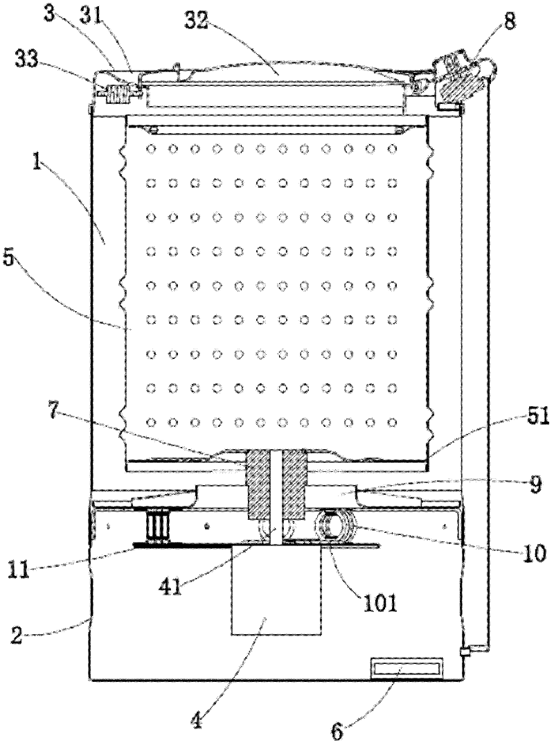
[0017] Such as figure 1 As shown, the suspension type dehydrator provided by the present invention includes a cover frame part 3, a barrel body 1, a rotating cage 5, a base 2 and a motor 4, the barrel body 1 is fixed on the base 2, and the water is conveniently collected and discharged, and the base 2 Electrical components 6 are installed inside, the cover frame part 3 is fixed on the upper end of the barrel body 1, a dehydration timer 8 is installed on the cover frame part 1 to cooperate with the electrical components 6, the motor 4 is located in the base 2, and the rotating cage 5 is located in the barrel body 1, the bottom plate 51 of the tumbler 5 is welded with a connecting bushing 7, the motor shaft 41 cooperates with the connecting bushing 7, the tumbler 5 is driven by the motor 4 to rotate at a high speed, the joint between the base 2 and the barrel body 1 A base end plate 13 is fixedly installed, and a motor mounting plate 11 is fixedly installed in the base 2. Severa...

Embodiment 2

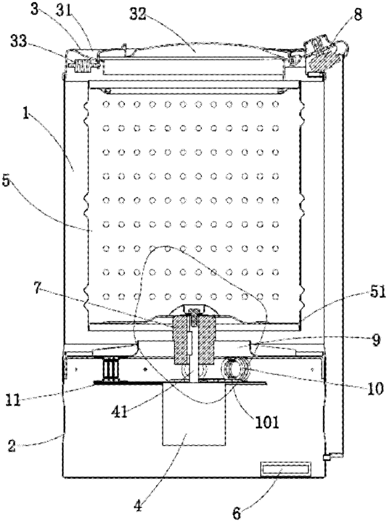
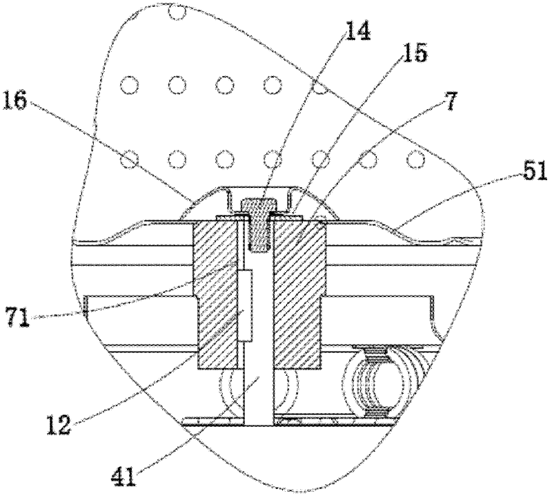
[0020] Such as figure 2 , image 3 As shown, the general structure of the suspension dehydrator provided in this embodiment is consistent with that of Embodiment 1, but in order to facilitate disassembly and maintenance, the linkage between the motor shaft 41 and the connecting sleeve 7 is a key fit structure, and the connecting sleeve 7 The inner wall is provided with a keyway 71, and the motor shaft 41 fixed with the key 12 penetrates the connecting bushing 7, and the key 12 on the motor shaft 41 cooperates with the keyway 71 on the inner wall of the connecting bushing 7; in order to protect the motor 4, the connecting bushing 7 A spacer element 15 is provided at the top of the inner hole, and the spacer element 15 is fixed to the motor shaft 41 by a fastener 14. The fastener 14 can be a screw or other fastening standard parts, and a mask is provided on the bottom plate of the cage 16 cooperates with spacer element 15.

Embodiment 3

[0022] Such as Figure 4 As shown, the general structure of the suspension dehydrator provided in this embodiment is consistent with that of Embodiment 1, but in order to strengthen the connection strength between the bottom plate 51 of the tumbler and the connecting sleeve 7, a lining plate is fixedly placed on the connecting sleeve 7 13. The lining plate 13 is welded with the connecting shaft sleeve 7, and also welded with the bottom plate 5 of the cage.


PUM


Abstract

The invention discloses a suspended dehydrator, comprising a cover frame part, a barrel body, a rotating cage, a base and a motor, wherein the barrel body is fixed on the base in which an electric component is arranged; the cover frame part is fixed at the upper end of the barrel body and is provided with a dehydration timer which is matched with the electric component; the motor is positioned inside the base; the rotating cage is positioned inside the barrel body; a connecting shaft sleeve is fixed on a rotating cage base plate at the bottom end of the rotating cage; a motor shaft is matchedwith the connecting shaft sleeve to form a link structure; a base end plate is arranged at the joint of the base and the barrel body; the base is internally provided with a motor mounting plate; a plurality of flexible connecting components are arranged between the base end plate and a motor mounting frame; each flexible connecting component is fixedly connected with the base end plate and the motor mounting plate by a fastening component; and the motor is fixed on the motor mounting plate. The base end plate is flexibly connected with the motor mounting plate to absorb the vibration generated by the motor during working, so that the whole machine is stable during working, and the working speed can be increased to 1,200r/min.

Description

technical field [0001] The invention relates to a dehydrator, especially a suspension dehydrator. Background technique [0002] The dehydrator is a kind of dehydration equipment, which can dehydrate clothes, bedding and other fabrics with high efficiency, and can be used in hotels, hospitals, schools, laundry rooms and other public places. [0003] In order to achieve the purpose of shock absorption, the traditional dehydrator needs to be installed on the ground and connected to the ground. At the same time, due to the impact of vibration during work, the traditional dehydrator generally works at a speed below 800r / min, and the dehydration efficiency is low. Contents of the invention [0004] The object of the present invention is to provide a suspension type dehydrator with small working vibration in order to solve the above-mentioned deficiencies in the prior art. [0005] In order to achieve the above object, the suspension type dehydrator designed by the present inven...

Claims


Application Information

Patent Timeline
Patent Type & Authority Applications(China)
IPC IPC(8): D06F49/06D06F49/04D06F49/00
Inventor 乐建荣
Owner 宁波乐士洗涤科技有限公司
Why Eureka
Try Eureka