
Concentric pipe wellhead device for exploiting thickened oil through steam assisted gravity drainage

An auxiliary gravity and wellhead device technology, which is applied in earthwork drilling, wellbore/well components, sealing/isolation, etc., can solve the influence of temperature and pressure testing, can not measure wellbore temperature and pressure in real time, and is not used for testing and other issues to achieve the effect of ensuring safe and stable work

Active Publication Date: 2014-06-04
PETROCHINA CO LTD
View PDF1 Cites 0 Cited by
  • Summary
  • Abstract
  • Description
  • Claims
  • Application Information

AI Technical Summary

Problems solved by technology

However, in the application of SAGD production in heavy oil horizontal wells, since the wellhead devices (SAGA thermal recovery wellhead and thermal recovery double-tube wellhead) for heavy oil horizontal well SAGD production can only hang two tubing, when using the dual-tube self-spraying process, there is no The independent pipe string is used as a test, and the test is carried out in the self-spraying or production pipe string, which has a certain impact on the temperature and pressure test, and the temperature and pressure in the wellbore cannot be measured in real time. Therefore, a new production method - concentric double Pipe self-spraying production, two concentric double pipes are used as channels for self-spraying production, and the auxiliary pipe is used as a test tube for separate temperature and pressure tests

Method used


Image

  • Concentric pipe wellhead device for exploiting thickened oil through steam assisted gravity drainage
  • Concentric pipe wellhead device for exploiting thickened oil through steam assisted gravity drainage
  • Concentric pipe wellhead device for exploiting thickened oil through steam assisted gravity drainage

Examples


Embodiment 1

[0029] Embodiment 1: Taking a concentric tube wellhead device for heavy oil recovery by steam-assisted gravity drainage as an example, the present invention will be further described in detail.

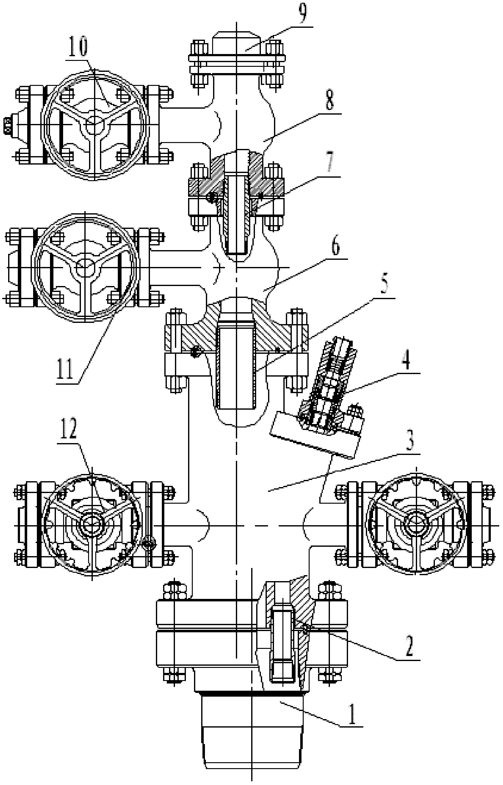
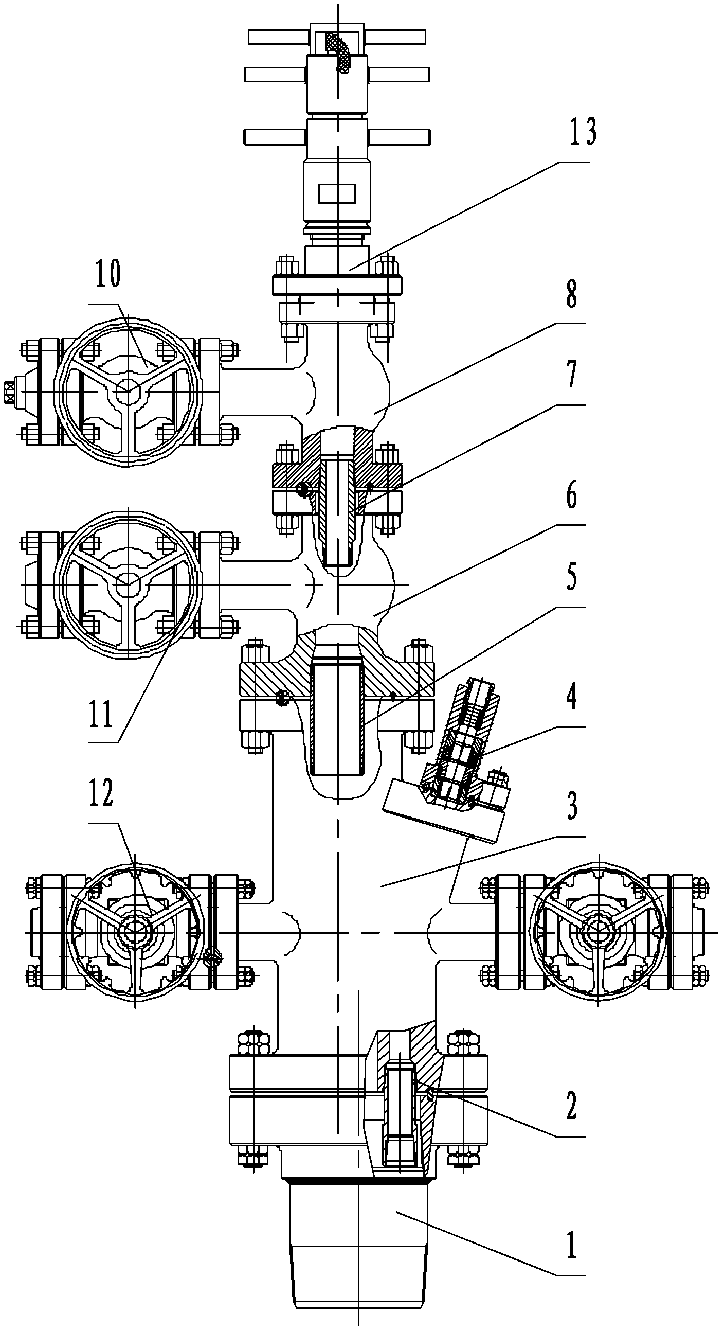
[0030] refer to figure 1 . The concentric pipe wellhead device used in steam-assisted gravity drainage to exploit heavy oil is mainly composed of a casing flange nipple 1, a test tubing suspension nipple 2, a large cross 3, a coiled tubing suspension sealing device 4, and an outer tubing suspension Puppet 5, outer pipe small tee 6, inner oil pipe suspension nipple 7, inner pipe small tee 8, wax removal gate valve 9, inner pipe production or steam injection gate valve 10, outer pipe production or steam injection gate valve 11 and casing gate valve 12 composition.

[0031] The lower end of casing flange pup joint 1 has 9 5 / 8 BCSG (outer diameter 244.5mm) (the standard used in China is the national standard of the People's Republic of China "Processing, Measurement and Inspection o...


PUM


Abstract

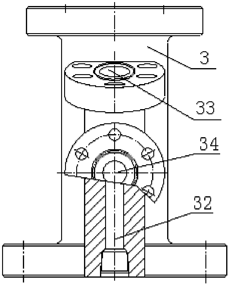
The invention discloses a concentric pipe wellhead device for exploiting thickened oil through steam assisted gravity drainage, and the device is used in the technical field of thermal recovery production for thickened oil in an oil field. The two sides of a large cross are respectively connected with a sleeve gate valve through flanges; and a columnar eccentric main channel and an auxiliary channel are arranged in the large cross; an outer pipe small tee joint and an outer pipe production or steam injection gate valve are fixed at the upper end of the large cross through flanges; an outer oil pipe hanging short section is fixed at the lower end of the outer pipe small tee joint through an internal thread; an inner pipe small tee joint and an inner pipe production or steam injection gate valve are fixed at the upper end of the outer pipe small tee joint; an inner oil pipe hanging short section is fixed at the lower end of the inner pipe small tee joint through an internal thread; and a paraffin removal gate valve or polish rod sealer is fixed at the upper end of the inner pipe small tee joint. The device has the effects of meeting the technical requirements of the steam injection, automatic flow, oil pumping and test processes in thermal recovery of thickened oil, and realizing two-point steam injection, one-point circular liquid discharge and real-time test through an independent auxiliary pipe test channel.

Description

technical field [0001] The invention relates to the technical field of oilfield heavy oil thermal recovery production, in particular to a wellhead device for heavy oil thermal recovery production wells, which is a concentric tube wellhead device for heavy oil recovery by SAGD technology. Background technique [0002] Steam-assisted gravity drainage (SAGD) technology is a cutting-edge technology for the development of super-heavy oil. Its mechanism is to inject steam into the steam injection well, and the steam overlaps upwards in the formation to form a steam cavity. The steam cavity expands upward and sideways, and the oil layer The crude oil in the tank undergoes heat exchange, and the heated crude oil and steam condensate are released to the horizontal production well below by gravity. Using SAGD technology to develop super heavy oil has become a mature technology for super heavy oil development in the world. [0003] Wellheads using Steam Assisted Gravity Drainage (SAGD...

Claims


Application Information

Patent Timeline
Patent Type & Authority Patents(China)
IPC IPC(8): E21B33/03
Inventor 郭文德袁新生窦升军游红娟陈森
Owner PETROCHINA CO LTD
Learn More