Variable burning rate synergistic perforating charge

A technology of charging and burning rate, which is applied in the direction of mining fluid, wellbore/well components, earthwork drilling and mining, etc. It can solve the problems of unreasonable charging structure, insufficient ignition, incomplete combustion, etc., and achieve the detonation time Long-lasting, less prone to accidents, and low ignition energy

Active Publication Date: 2011-12-21
ZHONGBEI UNIV
View PDF5 Cites 7 Cited by
  • Summary
  • Abstract
  • Description
  • Claims
  • Application Information

AI Technical Summary

Problems solved by technology

[0005] The purpose of the present invention is to solve the problems of insufficient ignition, incomplete combustion, short action time and low gas production in the existing conventional composite perforation technology due to its single charge and unreasonable charge structure. Therefore, the present invention provides A variable burning rate synergistic perforating charge is developed. The charge of the present invention adopts a multi-stage variable burning rate compound charge composed of ignition charge, delay charge, speed-up charge and deflagration charge, which can achieve step-variable combustion The purpose of increasing speed and efficiency, the present invention is simple in structure and easy to operate, which can greatly increase the number, length and flow conductivity of oil layer fractures, thereby improving the production efficiency of oil and gas wells

Method used


Image

  • Variable burning rate synergistic perforating charge
  • Variable burning rate synergistic perforating charge
  • Variable burning rate synergistic perforating charge

Examples


Embodiment 1

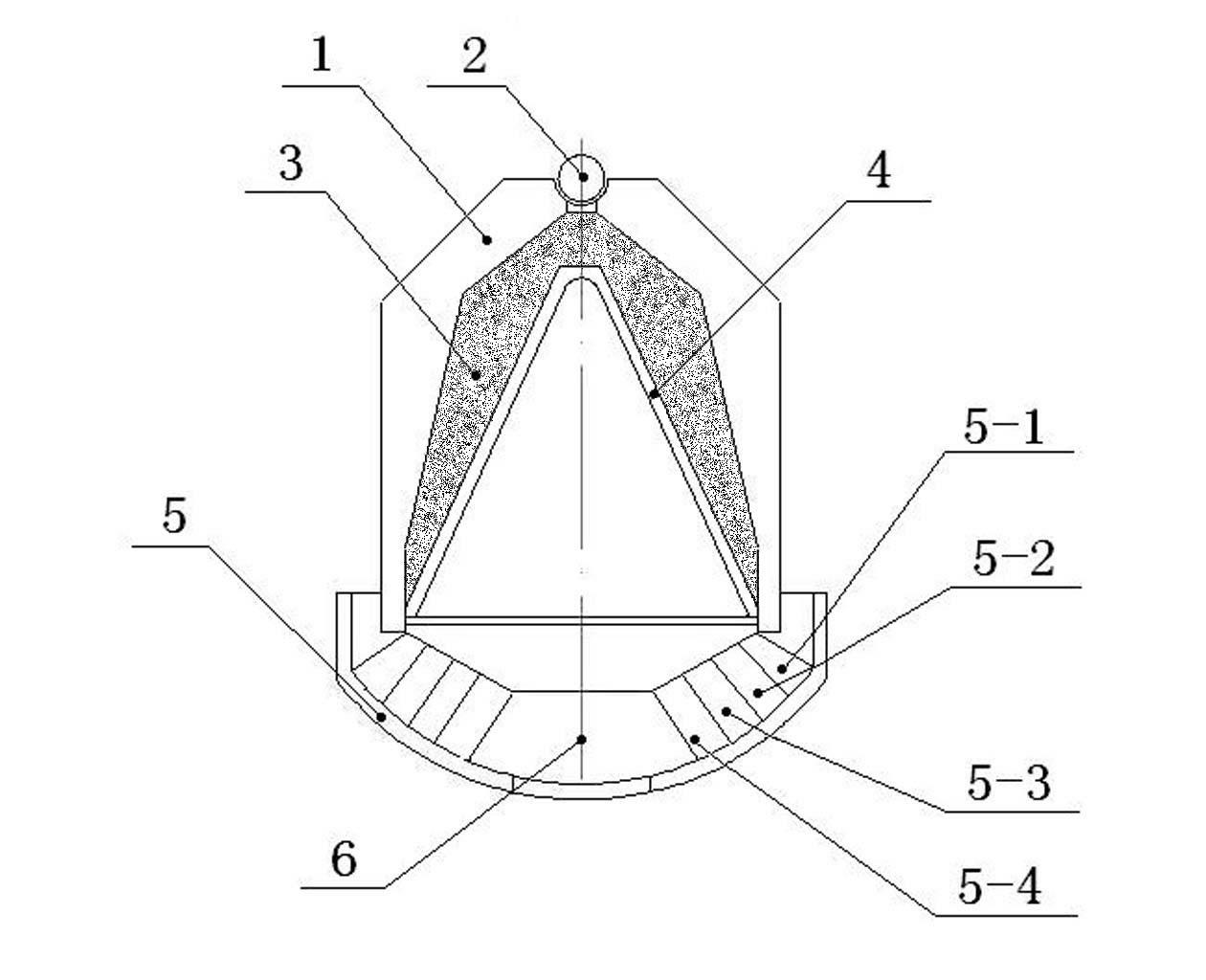
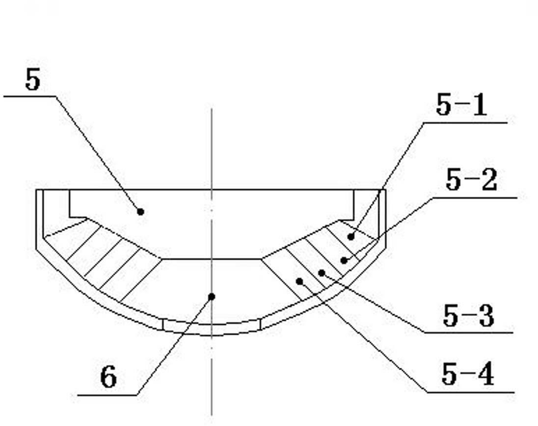
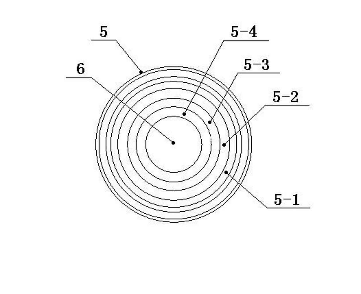
[0017] A variable burning rate synergistic perforating charge, including a perforating charge and a charge front chamber 5, the perforating charge includes a shell 1 with a detonating cord 2 on the top, a drug cover 4 inside the shell 1, and a filling The high-energy explosive 3 installed between the cartridge case 1 and the liner 4, the charge front chamber 5 is tightly socketed on the port of the inner cavity of the perforating charge, and the center of the concave bottom plate of the charge front chamber 5 is provided with a The jet channel 6 communicating with the inner cavity of the bullet, and the centerlines of the cartridge case 1, the drug-type cover 4 and the jet channel 6 are on the same axis; wherein, the inside of the charge front chamber 5 is from the periphery to the jet channel 6 by a height To the bottom, a circular ring-shaped ignition powder circle 5-1, a time-delay medicine circle 5-2, a speed-up medicine circle 5-3 and a deflagration medicine circle 5-4 are...

Embodiment 2

[0020] A variable burning rate synergistic perforating charge, including a perforating charge and a charge front chamber 5, the perforating charge includes a shell 1 with a detonating cord 2 on the top, a drug cover 4 inside the shell 1, and a filling The high-energy explosive 3 installed between the cartridge case 1 and the liner 4, the charge front chamber 5 is tightly socketed on the port of the inner cavity of the perforating charge, and the center of the concave bottom plate of the charge front chamber 5 is provided with a The jet channel 6 communicating with the inner cavity of the bullet, and the centerlines of the cartridge case 1, the drug-type cover 4 and the jet channel 6 are on the same axis; wherein, the inside of the charge front chamber 5 is from the periphery to the jet channel 6 by a height To the bottom, a circular ring-shaped ignition powder circle 5-1, a time-delay medicine circle 5-2, a speed-up medicine circle 5-3 and a deflagration medicine circle 5-4 are...

Embodiment 3

[0023] A variable burning rate synergistic perforating charge, including a perforating charge and a charge front chamber 5, the perforating charge includes a shell 1 with a detonating cord 2 on the top, a drug cover 4 inside the shell 1, and a filling The high-energy explosive 3 installed between the cartridge case 1 and the liner 4, the charge front chamber 5 is tightly socketed on the port of the inner cavity of the perforating charge, and the center of the concave bottom plate of the charge front chamber 5 is provided with a The jet channel 6 communicating with the inner cavity of the bullet, and the centerlines of the cartridge case 1, the drug-type cover 4 and the jet channel 6 are on the same axis; wherein, the inside of the charge front chamber 5 is from the periphery to the jet channel 6 by a height To the bottom, a circular ring-shaped ignition powder circle 5-1, a time-delay medicine circle 5-2, a speed-up medicine circle 5-3 and a deflagration medicine circle 5-4 are...


PUM


Abstract

The invention discloses a variable-burning rate synergistic perforating propellant which can be used for solving the problems of insufficient ignition, incomplete burning, short acting time and small amount of gas production resulting from the single propellant and unreasonable propellant structure of the conventional composite perforation technology. The variable-burning rate synergistic perforating propellant disclosed by the invention comprises a perforating bullet and a propellant front bin which is mounted at the port of the inner cavity of the perforating bullet, wherein a jet flow channel is arranged in the center of the bottom plate of the propellant front bin; an ignition powder coil, a delay powder coil, a speed-up powder coil and a deflagration powder coil are sequentially arranged from high to low between the circumference and the jet flow channel in the propellant front bin; the four powder coils have the same height at a width ratio of (1-2):(2-4):(2-4):(10-15); and the four powder coils consist of powder of four different formulas and can realize gradual variable-burning rate synergy from the ignition powder coil to the deflagration powder coil. The variable-burning rate synergistic perforating propellant disclosed by the invention has the advantages of simple structure, low ignition power, strong burning resistance and long blast acting time, is convenient to operate, has the reaming pressure increased by 60%, can at least double the synergistic time, and be used for remarkably improving the producing efficiency of an oil gas well.

Description

technical field [0001] The invention belongs to the technical field of petroleum development, and relates to a composite perforating device used for perforating, fracturing and removing plugs of oil wells, in particular to a variable combustion rate and synergistic perforation charge. Background technique [0002] For production wells and old wells in oil fields, with the increase of production time and perforation times, the situation around the original perforated section of the oil layer will change greatly, and the pores and fractures in the near well zone will be destroyed by the organic matter in the oil layer. , High molecular polymers, downhole microorganisms and bacteria are clogged and become increasingly serious, resulting in increasing seepage resistance, which leads to a gradual decrease in oil well production and even shutdown. Therefore, various plugging removal measures can only be used to remove the blockage near the wellbore, and then restore and increase t...

Claims


Application Information

Patent Timeline
Patent Type & Authority Applications(China)
IPC IPC(8): E21B43/116E21B43/119
Inventor 刘天生张晋红刘迎彬李如江王凤英高永宏胡晓艳陶志龙
Owner ZHONGBEI UNIV
Why Eureka
Try Eureka