A sealing and lubricating structure for the plunger of an ultra-high pressure plunger pump

A plunger pump, ultra-high pressure technology, applied to parts of pumping devices for elastic fluids, pump elements, variable displacement pump parts, etc., can solve fuel leakage, leakage, plunger and plunger sleeve wear failure and other problems to achieve the effect of overcoming wear

Active Publication Date: 2011-12-21
上海夏雪科技有限公司
View PDF6 Cites 9 Cited by
  • Summary
  • Abstract
  • Description
  • Claims
  • Application Information

AI Technical Summary

Problems solved by technology

The existing electronically controlled high-pressure fuel injection systems of diesel engines all use plunger-type high-pressure fuel pumps. The sliding fit gap between the plunger and the plunger sleeve depends on fuel oil lubrication and sealing. A ring-shaped pressure relief return tank is added to make the leaked fuel flow back to the fuel tank from the oil return tank through the oil return passage. The fuel leakage in the gap increases with the increase of the pump oil pressure. Severe fuel leakage makes it difficult to establish a super high pressure of more than 2000bar. Fuel pressure, the pump oil pressure of the current high-pressure fuel pump is in the range of 1600-1800bar, and rarely reaches 2000bar
In order to meet the requirements of reducing emissi

Method used


Image

  • A sealing and lubricating structure for the plunger of an ultra-high pressure plunger pump
  • A sealing and lubricating structure for the plunger of an ultra-high pressure plunger pump
  • A sealing and lubricating structure for the plunger of an ultra-high pressure plunger pump

Examples


Example Embodiment

[0019] The specific embodiments of the present invention will be further described below in conjunction with the accompanying drawings.

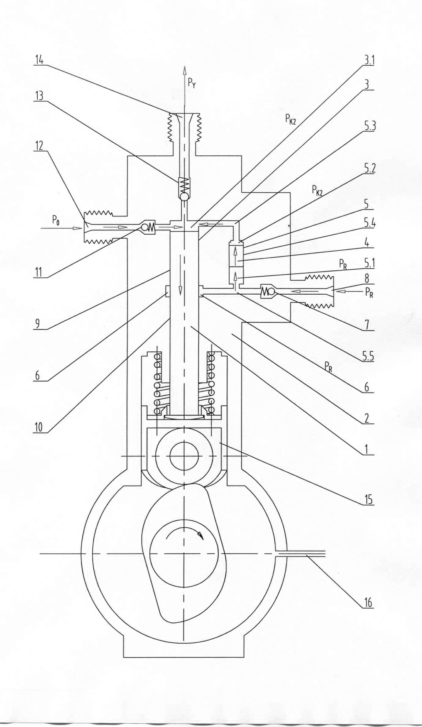
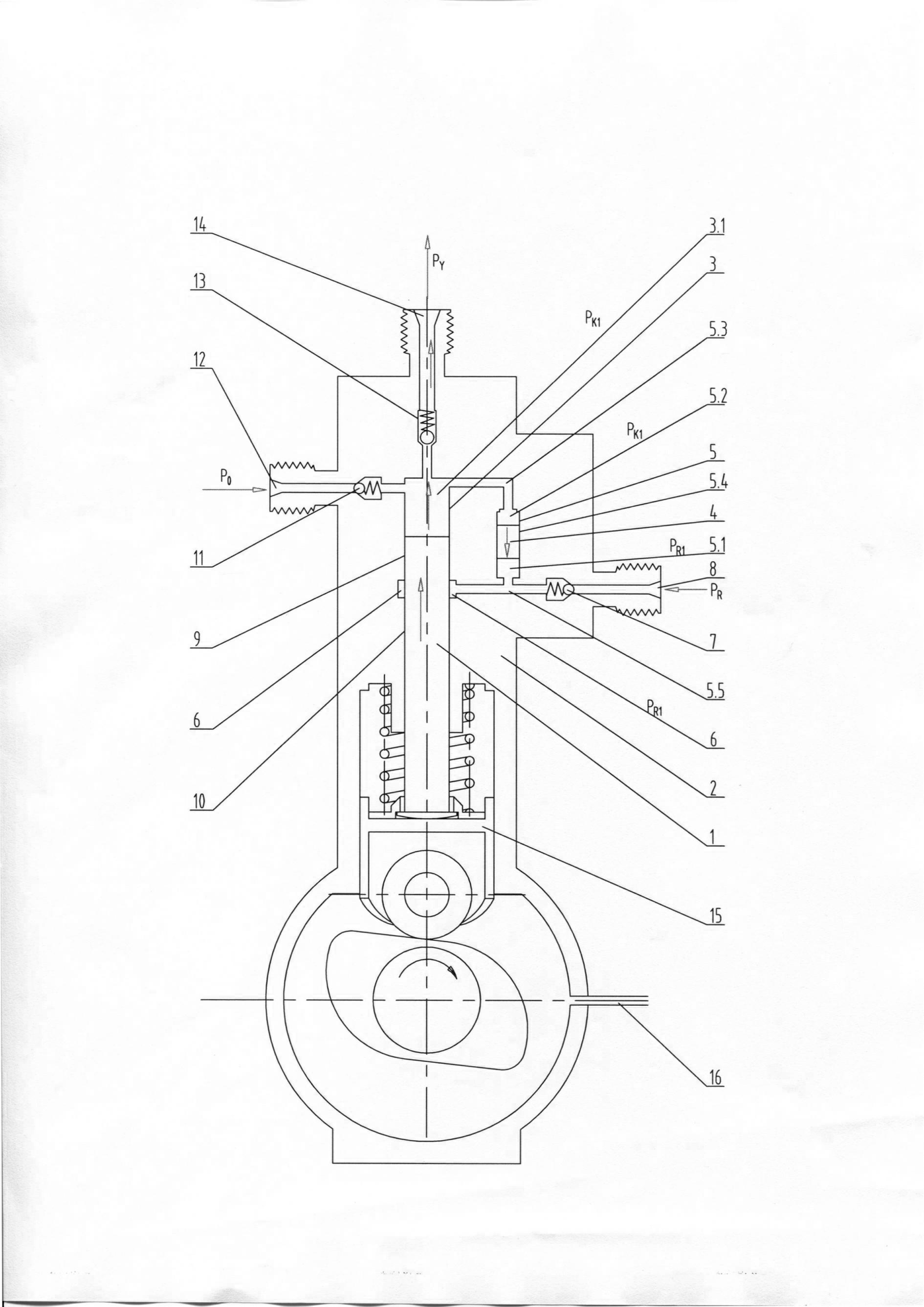
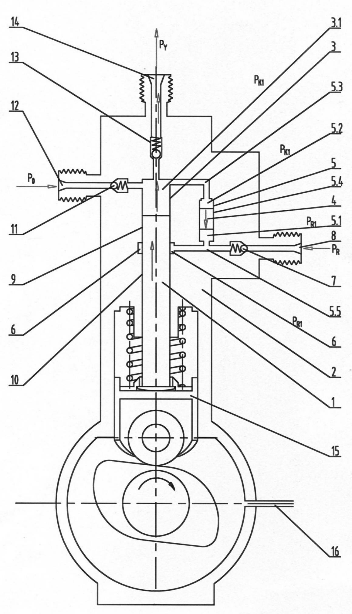
[0020] like figure 1 The sealing and lubricating structure of a plunger of an ultra-high pressure plunger pump of the present invention is shown, which mainly includes a plunger 1 and a cylinder body 2, and is characterized in that it also includes a pressure transmission cylinder 5 and a free pressure transmission cylinder 5. Piston 4, free piston 4 and pressure transmission cylinder 5 are slidingly matched to form a free piston annular micro gap 5.4, the free piston gap is 0.0015-0.0025 mm, and free piston 4 divides pressure transmission cylinder 5 into pressure transmission chamber 5.2 and lubricating oil Cavity 5.1; the precise sliding fit between the plunger 1 installed in the working cylinder hole 3 and the working cylinder hole 3 forms a plunger annular micro-gap, the gap is 0.0015 ~ 0.0025 mm, the upper top surface of the plunger 1 a...


PUM


Abstract

The invention relates to a sealing lubrication structure for a plunger of an ultrahigh pressure plunger pump. The sealing lubrication structure mainly comprises a plunger, a cylinder, a pressure transfer oil cylinder and a free piston arranged in the pressure transfer oil cylinder. The free piston divides the pressure transfer oil cylinder into a pressure transfer cavity and a lubricating oil cavity. The sealing lubrication structure is characterized in that: an annular sealing oil groove formed on a working cylinder hole separates a plunger annular microgap between the plunger and the working cylinder hole into upper and lower plunger annular microgaps; when the plunger ascends to pump oil, the pressure of ultrahigh pressure fuel oil in a pump cavity is transferred to the annular oil groove through an oil duct, the pressure transfer cavity, the free piston, the lubricating oil cavity and a three-way oil duct, so that the pressure of the pump cavity is equal to that of the annular sealing oil groove; and a small amount of lubricating oil leaks from the annular sealing oil groove through the lower plunger annular microgap, and under the action of the pressure of the fuel oil in the pump cavity, the free piston descends to supplement the leaked lubricating oil to keep the pressure of the lubricating oil in the annular sealing oil groove at the lower end of the annular microgap equal to that of the fuel oil in the pump cavity at the upper end so as to effectively prevent the fuel oil from leaking through the annular microgap and overcome the wear between the plunger and the working cylinder hole.

Description

technical field [0001] The invention relates to a diesel engine high-pressure fuel pump and an ultra-high-pressure water pump, in particular to a sealing and lubricating structure for a plunger of an ultra-high-pressure plunger pump. technical background [0002] Existing ultra-high-pressure water pumps are plunger-type water pumps. The development and application of high-pressure water jet cleaning, rust removal, and cutting technologies require ultra-high-pressure plunger-type water pumps with higher pressure and longer working life. The gap throttling step-down seal and packing seal used in the plunger type ultra-high pressure water pump cannot meet the needs of ultra-high pressure pump water above 2000bar, and its working life is short, the plunger life is only about 500 hours, and the sealing packing working life is only About 200 hours.. The sealing and lubrication of the plunger is a technical problem that needs to be solved in the ultra-high pressure water pump. ...

Claims


Application Information

Patent Timeline
IPC IPC(8): F04B53/18
Inventor 郑国璋郭建玲王淑平姚武朱建军林易徐淡晨
Owner 上海夏雪科技有限公司
Why Eureka
Try Eureka