End Tooth Electromagnetic Clutch

An electromagnetic clutch and end tooth technology, applied in clutches, magnetic drive clutches, non-mechanical drive clutches, etc., can solve the problems of low transmission ratio precision, short service life, large coil windings, etc., and achieve high transmission ratio precision and compact structure. , The effect of large transmission torque

Inactive Publication Date: 2011-12-21
王万年
View PDF7 Cites 19 Cited by
  • Summary
  • Abstract
  • Description
  • Claims
  • Application Information

AI Technical Summary

Problems solved by technology

The traditional domestic electromagnetic clutch is a friction clutch plate structure, complex structure, large coil winding, bulky body, low transmission ratio accuracy, high failure rate, frequent adjustment and maintenance, and short service life

Method used


Image

  • End Tooth Electromagnetic Clutch
  • End Tooth Electromagnetic Clutch
  • End Tooth Electromagnetic Clutch

Examples


Embodiment Construction

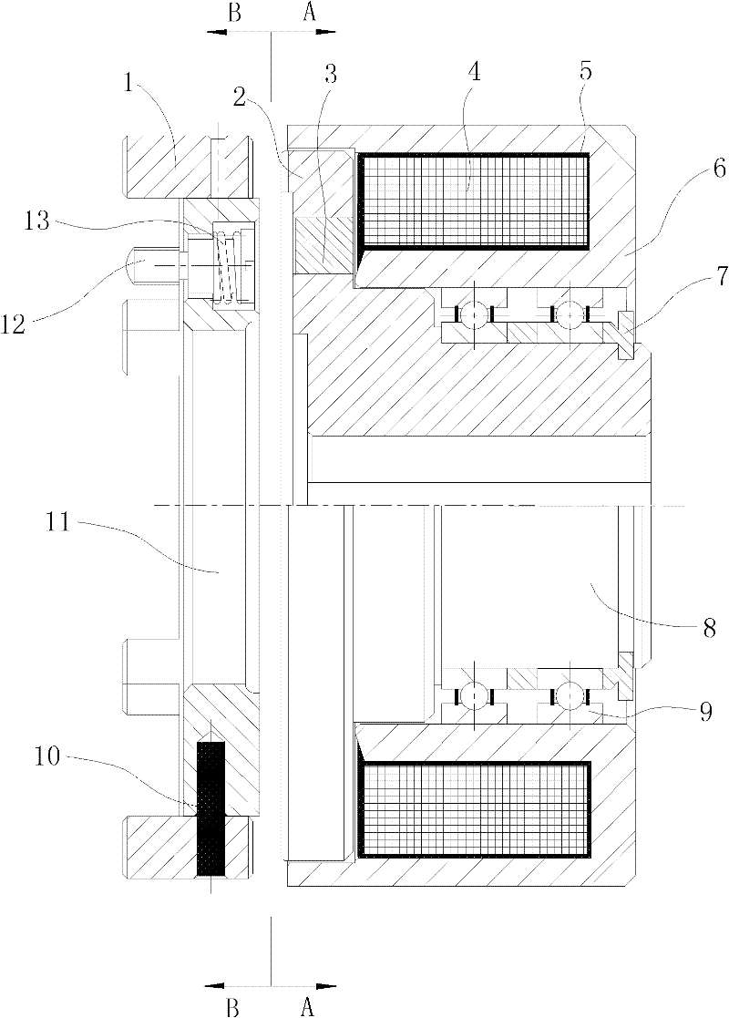
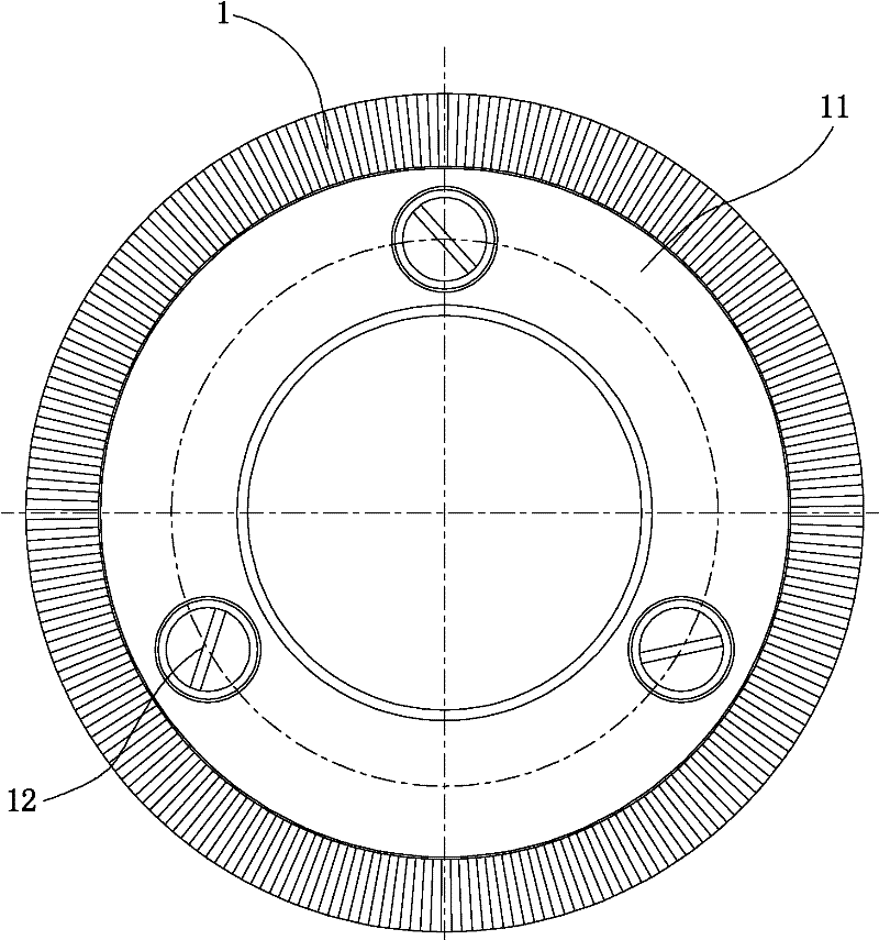
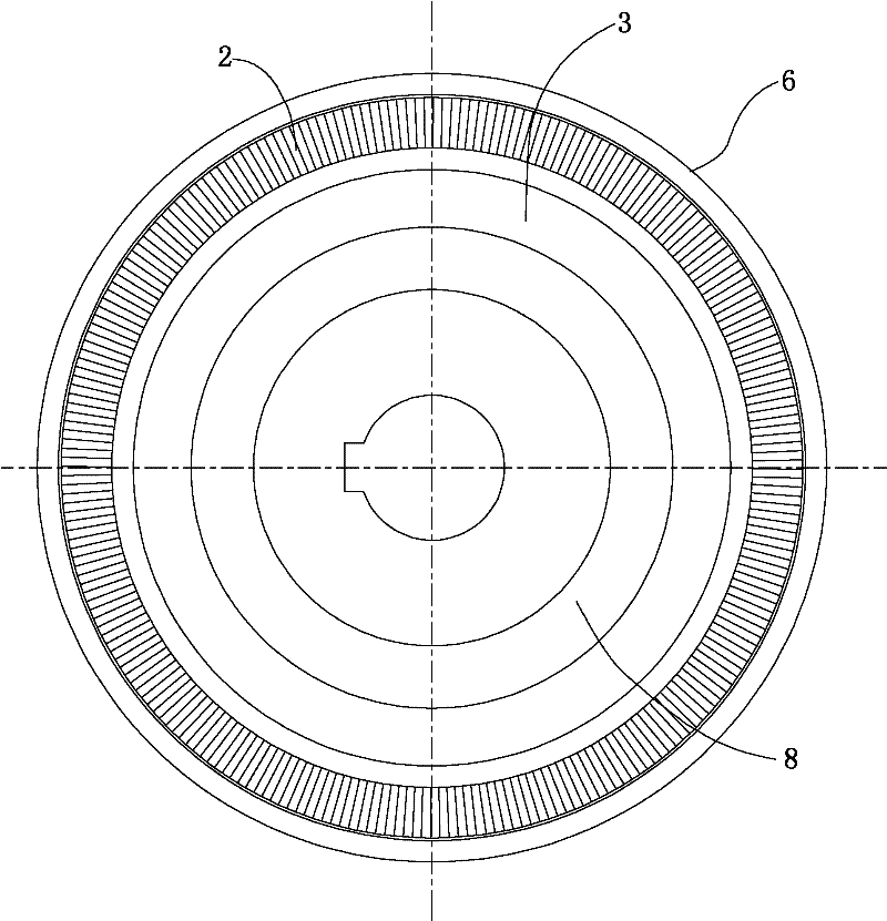
[0020] The implementation of the present invention will be further described below in conjunction with the accompanying drawings. figure 1 It is a structural schematic diagram of an embodiment of the end-tooth electromagnetic clutch provided by the present invention, figure 2 , image 3 respectively figure 1 The B-B and A-A orientation views. This embodiment is a clutch used for fast and accurate conversion of electric energy and mechanical energy in industrial production to obtain torque transmission. It can be seen from the figure that the end gear shaft 2, the magnetic isolation ring 3, and the core shaft 8 are assembled into the end gear shaft, which is set in two 6807 bearings 9, positioned axially by the retaining ring 7, and then assembled on the coil wrapped by insulating paper 5. 4. Place it in the yoke 6 as the active part; then rivet the armature flange 11 in the end tooth clutch claw 1 with a hollow pin 10, and set the spring 13 on the M4 screw 12 to fix the ar...


PUM


Abstract

The invention belongs to the technical field of electromagnetic clutches, and relates to an end tooth electromagnetic clutch. The end-tooth electromagnetic clutch includes a driving part and a driven part. The clutch claw, armature flange, and spring are composed of an end gear ring, a magnetic isolation ring, and a core shaft to assemble an end gear shaft, which is set in two 6807 bearings, axially positioned by a retaining ring, and assembled in the inner hole of the yoke. The coil wrapped by insulating paper is placed in the coil groove of the yoke; the armature flange is riveted in the end tooth clutch claw with a hollow pin, and the spring is set on the screw. The end-tooth electromagnetic clutch adopts end-tooth gear connection to transmit power. It has the advantages of simple structure, convenient installation and maintenance, and high transmission ratio precision, which effectively ensures the fast and accurate conversion of mechanical energy in industrial production and the transmission of torque.

Description

technical field [0001] The invention belongs to the technical field of electromagnetic clutches, and relates to an end-tooth electromagnetic clutch used in industrial production to convert electric energy into mechanical energy (torque) for transmission and braking. Background technique [0002] At present, the domestic pharmaceutical, food, chemical, light industry, tobacco and other industries have higher and higher requirements for automatic production, and higher and higher requirements for the transmission mechanism in the production process: 1 compact structure, large transmission torque; 2 transmission ratio Precise, durable; 3 sensitive and quick action, easy to install and maintain. The traditional domestic electromagnetic clutch is a friction clutch plate structure, with complex structure, large coil winding, bulky body, low transmission ratio accuracy, high rotation failure rate, frequent adjustment and maintenance, and short service life. Contents of the invent...

Claims


Application Information

Patent Timeline
Patent Type & Authority Applications(China)
IPC IPC(8): F16D27/09F16D27/14
Inventor 王万年
Owner 王万年
Why Eureka
Try Eureka