Automatic detection device for pyrotechnics

An automatic detection device and a technology for pyrotechnics, which are used in measuring devices, measuring electrical variables, measuring resistance/reactance/impedance, etc., and can solve problems such as large manual tasks.

Inactive Publication Date: 2011-12-21
BEIJING INST OF ELECTRONICS SYST ENG
View PDF3 Cites 23 Cited by
  • Summary
  • Abstract
  • Description
  • Claims
  • Application Information

AI Technical Summary

Problems solved by technology

[0003] The purpose of the present invention is to provide an automatic detection device for pyrotechnics to solve the problem of a large amount of tasks in manual point-by-point detection

Method used


Image

  • Automatic detection device for pyrotechnics
  • Automatic detection device for pyrotechnics

Examples


specific Embodiment approach 1

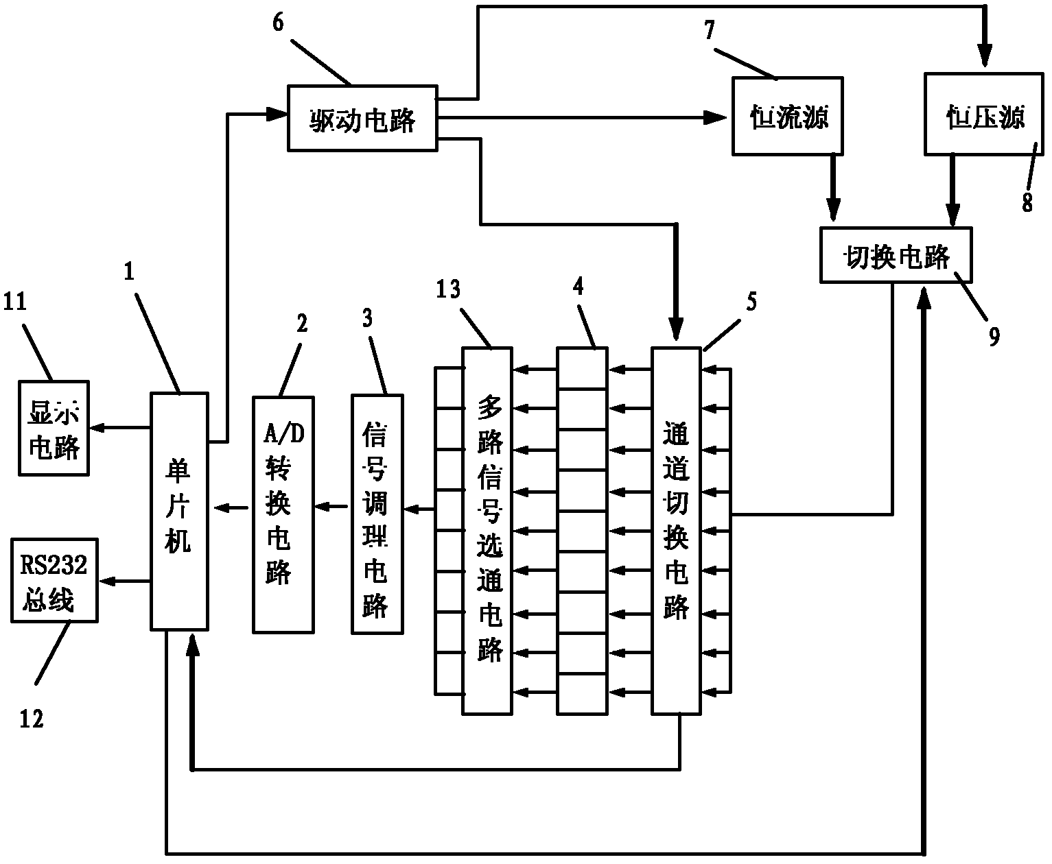
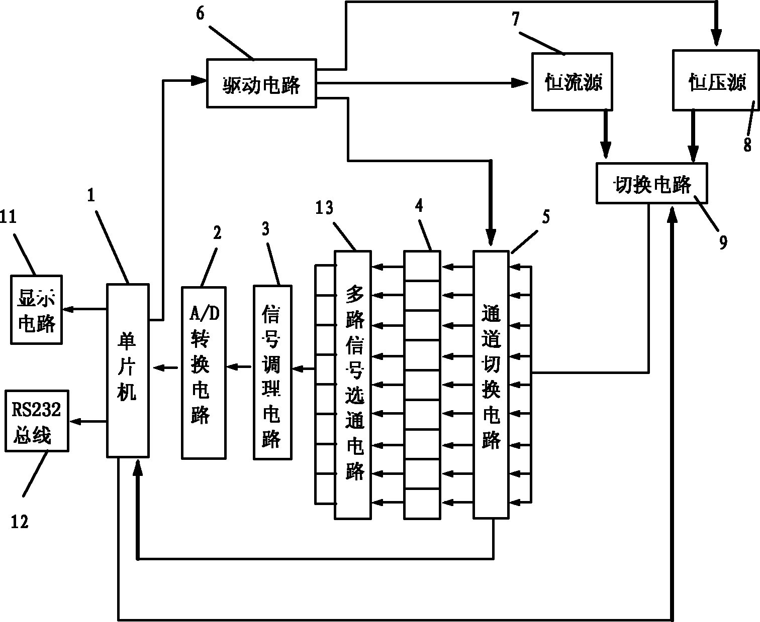
[0006] Specific implementation mode one: the following combination figure 1 This embodiment will be specifically described. This embodiment includes single-chip microcomputer 1, A / D conversion circuit 2, signal conditioning circuit 3, channel switching circuit 5, drive circuit 6, constant current source 7, display circuit 11 and multi-channel signal gating circuit 13, the signal of display circuit 11 The input end is connected to the display signal output end of the single-chip microcomputer 1, the data signal input end of the single-chip microcomputer 1 is connected to the data signal output end of the A / D conversion circuit 2, and the data signal input end of the A / D conversion circuit 2 is connected to the signal output of the signal conditioning circuit 3 The signal input end of the signal conditioning circuit 3 is connected to each signal output end of the multi-channel signal gating circuit 13, and each signal input end of the multi-channel signal gating circuit 13 is co...

specific Embodiment approach 2

[0007] Specific implementation mode two: the following combination figure 1 This embodiment will be specifically described. The difference between this embodiment and Embodiment 1 is that the channel switching circuit 5 is a relay switch array, and each relay forming the relay switch array has a switch state output terminal, and the switch state output terminal is connected to the state of the single chip microcomputer 1. on the signal input. With such setting, the resistance value signal collected by the single-chip microcomputer 1 and the detected branch can be accurately corresponded one by one to avoid confusion.

specific Embodiment approach 3

[0008] Specific implementation mode three: the following combination figure 1 This embodiment will be specifically described. The difference between this embodiment and Embodiment 1 is that it also includes a constant voltage source 8 and a switching circuit 9, another output end of the drive circuit 6 is connected to the input end of the constant voltage source 8, and the constant current source 7 and the constant voltage source 8 The output ends are respectively connected to an input end of the switching circuit 9, the output end of the switching circuit 9 is connected to the signal input end of each channel of the channel switching circuit 5, and another control signal output end of the single-chip microcomputer 1 is connected to the controlled channel of the switching circuit 9. end. The single chip microcomputer 1 can also adjust the output values ​​of the constant current source 7 and the constant voltage source 8 through the drive circuit 6 .


PUM


Abstract

An automatic detection device for pyrotechnics, the invention relates to a detection device for resistance and insulation state of pyrotechnics. In order to solve the problem of a large amount of manual point-by-point detection tasks. for detection. It includes single-chip microcomputer, A / D conversion circuit, signal conditioning circuit, channel switching circuit, drive circuit, constant current source, display circuit and multi-channel signal gating circuit. The circuit is connected to each signal output end of the multi-channel signal gating circuit, and each signal input end of the multi-channel signal gating circuit is connected to each signal output end of the detected circuit one by one, and each signal input end of the detected circuit is one by one. One is connected to the signal output end of each channel of the channel switching circuit, the signal input end of each channel of the channel switching circuit is connected to the signal output end of the constant current source, and the controlled end of the channel switching circuit is connected to the On the drive signal output terminal of the single chip microcomputer.

Description

technical field [0001] The invention relates to a detection device for resistance and insulation state of pyrotechnics. Background technique [0002] Before the rocket is launched, the resistance and insulation status of the circuit in the rocket's ignition device should be tested. The general term for disposable components and devices that are filled with gunpowder or explosives, burn or explode after being stimulated by the outside world to ignite gunpowder, detonate explosives, or perform mechanical work is called pyrotechnics, so it is also called "pyrotechnics". "Detection. Since the number of endpoints that need to detect resistance and insulation status in actual work is very large, and pyrotechnics are the most sensitive part of the system, their safety and reliability directly affect the safety and reliability of the weapon system. The amount of detection tasks is very large, and manual testing is prone to misoperation, so a device is needed to automatically compl...

Claims


Application Information

Patent Timeline
Patent Type & Authority Applications(China)
IPC IPC(8): G01R27/14
Inventor 顾彬彬周兴邹磊李存洲邵玉峰朱瑾
Owner BEIJING INST OF ELECTRONICS SYST ENG
Why Eureka
Try Eureka