Apparatus and method for generating a beam of neutral particles

A particle beam and neutral technology, applied in the direction of discharge tubes, accelerators, electrical components, etc., can solve the problems that cannot meet the etching process, and achieve the effect of improving the neutralization efficiency

Active Publication Date: 2011-12-21
AEROTECH BEIJING
View PDF2 Cites 4 Cited by
  • Summary
  • Abstract
  • Description
  • Claims
  • Application Information

AI Technical Summary

Problems solved by technology

This will cause CF4, Ar ions and O oxygen ions not to be neutralized at the same time, which cannot meet the specific etching process

Method used


Image

  • Apparatus and method for generating a beam of neutral particles
  • Apparatus and method for generating a beam of neutral particles
  • Apparatus and method for generating a beam of neutral particles

Examples


Embodiment Construction

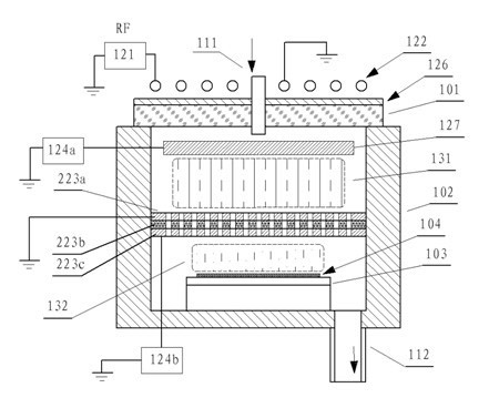
[0027] Such as image 3 As shown, the device for generating a neutral particle beam provided by the embodiment of the present invention includes a reaction chamber 102, an air inlet 111, a radio frequency power supply 121, a planar helical radio frequency coil 122, a Faraday shielding grid 126, a plasma source 131, and an exhaust port 112. The slide table 103, the chip 104, the upper plate 127, the middle plate 223a, the insulating plate 223b and the lower plate 223c. The upper board 127 is disposed above the plasma source 131 . Between the plasma source 131 and the slide stage 103, a middle grid plate 223a, an insulating plate 223b and a lower grid plate 223c are sequentially arranged. The upper board 127 is connected with a DC bias voltage DC1. The mid-screen board 223a is grounded. The lower screen plate 223c is supplied with a DC bias voltage DC2. Cylindrical, hexagonal, rhombic or other shaped holes run through the middle mesh plate 223a, the insulating plate 223b and...


PUM


Abstract

The invention discloses a device for producing a neutral particle beam, which comprises a reaction chamber, a slide glass table, a plasma source and an upper mesh plate. The slide glass table, the plasma source and the upper mesh plate are arranged on a chip and in the reaction chamber, the upper mesh plate is arranged on the plasma source, and an intermediate mesh plate, an insulating plate and a lower mesh plate are sequentially arranged between the plasma source and the slide glass table; and the upper mesh plate and the lower mesh plate are respectively connected with direct-current bias voltage, and the intermediate mesh plate is grounded. The invention also discloses a method for producing the neutral particle beam. By adopting the device for producing the neutral particle beam and the method thereof, positive ions and negative ions can be neutralized, the efficiency of ion neutralization can be improved, and different ions in mixed gases can achieve corresponding etching effects. The device and the method can adapt to different gas combinations and meet requirements of different etching processes.

Description

technical field [0001] The invention relates to the technical field of microfabrication of integrated circuits, micro-electromechanical systems (MEMS), solar energy and other thin films and body material surface processes, and in particular to a device and method for generating neutral particle beams. Background technique [0002] High product integration, refinement, high efficiency, and low cost have always been the direct driving force for the development of micro-processing manufacturing industries such as integrated circuits. Since 1970, device manufacturing first began to use plasma technology, which makes plasma technology a key technology for microfabrication in industrial fields such as large-scale integrated circuits (LSI). At present, plasma process technologies such as etching, ion implantation, cleaning, and deposition are widely used in the manufacturing process of VLSI. Plasma process technology, mainly for SiO 2 、Si x N y Microfabrication of dielectric f...

Claims


Application Information

Patent Timeline
Patent Type & Authority Applications(China)
IPC IPC(8): H01J37/32H05H3/00
CPCH01J37/321H01J37/32H05H3/00H01J37/32623H01J37/32422
Inventor 席峰李勇滔李楠张庆钊夏洋
Owner AEROTECH BEIJING
Why Eureka
Try Eureka