
Method and device for channel state information feedback

A channel state information and channel technology, which is applied in wireless communication, electrical components, and error prevention/detection through diversity reception.

Inactive Publication Date: 2011-12-21
CHINA ACAD OF TELECOMM TECH
View PDF3 Cites 25 Cited by
  • Summary
  • Abstract
  • Description
  • Claims
  • Application Information

AI Technical Summary

Problems solved by technology

If it is required to use the same precoding vector in the entire 20M bandwidth range, the delay value between the two antennas should be less than 5ns, which is basically unrealizable

Method used


Image

  • Method and device for channel state information feedback
  • Method and device for channel state information feedback
  • Method and device for channel state information feedback

Examples


Embodiment Construction

[0021] Embodiments of the present invention are described in detail below, examples of which are shown in the drawings, wherein the same or similar reference numerals designate the same or similar elements or elements having the same or similar functions throughout. The embodiments described below by referring to the figures are exemplary only for explaining the present invention and should not be construed as limiting the present invention.

[0022] The present invention proposes that each CC is divided into several frequency subsets, and each subset is called a BS (Bandwidth Segment, bandwidth segment). The eNB instructs the UE to measure one or some BSs through control signaling, and the UE feeds back the CSI on the BSs according to the reporting mode configured by the upper layer.

[0023] In order to achieve the purpose of the present invention, the present invention discloses a method for channel state information feedback, including the following steps: user equipment U...


PUM


Abstract

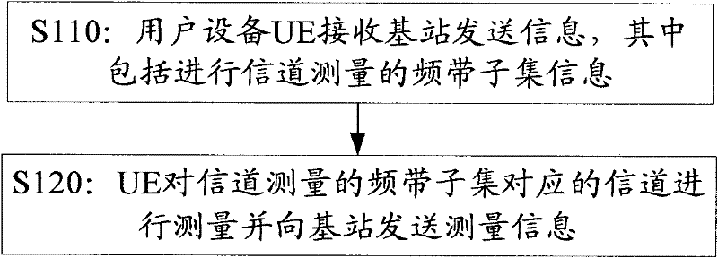
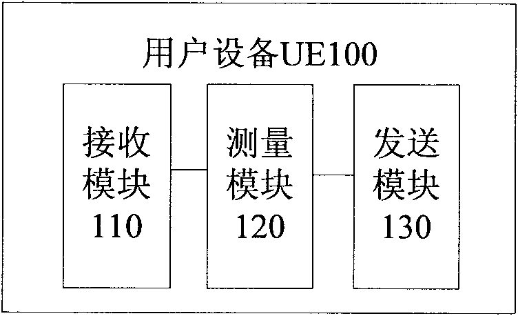
Embodiments of the present invention propose a method for channel state information feedback, including the following steps: a user equipment UE receives information sent by a base station, the information includes frequency band subset information for channel measurement; The channel corresponding to the frequency band subset is measured, and according to the channel measurement report mode configuration, the measurement information is sent to the base station through the physical uplink shared channel PUSCH. On the other hand, the embodiments of the present invention also propose a user equipment UE. The above solution proposed by the present invention solves the problem that the long-term / broadband PMI in the existing two-level feedback scheme can only feed back one wideband PMI for each CC, which will lead to loss of precoding performance in the case of large antenna calibration errors The problem.

Description

technical field [0001] The present invention relates to the field of mobile communication, in particular, the present invention relates to a method and equipment for channel state information feedback. Background technique [0002] Mobile and broadband have become the development direction of modern communication technology. 3GPP (3rd Generation Partnership Project) is committed to the evolution of LTE (Long Term Evolution, long-term evolution) system as a 3G system. The goal is to develop 3GPP wireless access technology towards Evolution for high data rate, low latency and optimized packet data applications. In a point-to-point communication system, if the transmitter can obtain a certain CSI (Channel State Information, channel state information), it can optimize the modulation mode, coding rate and spatial distribution characteristics of the signal power so that the transmission signal is consistent with the channel propagation characteristics. In this way, the effect of ...

Claims


Application Information

Patent Timeline
IPC IPC(8): H04W24/08H04L1/06
Inventor 苏昕高秋彬肖国军孙韶辉拉盖施
Owner CHINA ACAD OF TELECOMM TECH
Learn More