Multi-Frequency Oscillator with Dead Time in Electronic Ballasts

An electronic ballast and dead time technology, applied in the fields of multi-frequency oscillators and analog integrated circuits, can solve problems such as increased heat loss, unstable dead time, complex circuit structure, etc., to achieve extended life, process deviation and The effect of ambient temperature insensitivity

Active Publication Date: 2011-12-21
XIDIAN UNIV
View PDF4 Cites 13 Cited by
  • Summary
  • Abstract
  • Description
  • Claims
  • Application Information

AI Technical Summary

Problems solved by technology

[0007] 1. The circuit structure is complex and not easy to integrate;
[0008] 2. The minimum operating frequency generated by the circuit is fixed. If the resistance characteristics of the filament are changed, the light efficiency of the fluorescent lamp will be deteriorated;
[0009] 3. When applied to electronic ballast chips, the output signal of the circuit needs to pass through the high-end dead zone generating circuit to obtain the high-end control signal and the low-end dead zone generating circuit to obtain the low-end control signal, and these two dead zone generating circuits are due to Inconsistently affected by process deviation and ambient temperature, resulting in unstable dead time
If the dead time is too small, the switching tube in the external inverter circuit cannot meet the zero-voltage conversion conditions when it is turned on, thereby increasing heat loss and even damaging the switching tube.

Method used


Image

  • Multi-Frequency Oscillator with Dead Time in Electronic Ballasts
  • Multi-Frequency Oscillator with Dead Time in Electronic Ballasts
  • Multi-Frequency Oscillator with Dead Time in Electronic Ballasts

Examples


Embodiment Construction

[0031] The specific implementation of the present invention will be described in detail below with reference to the accompanying drawings.

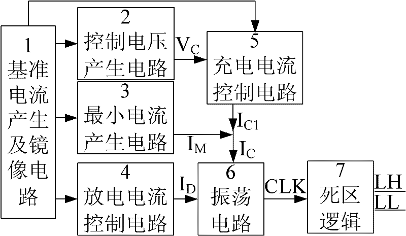
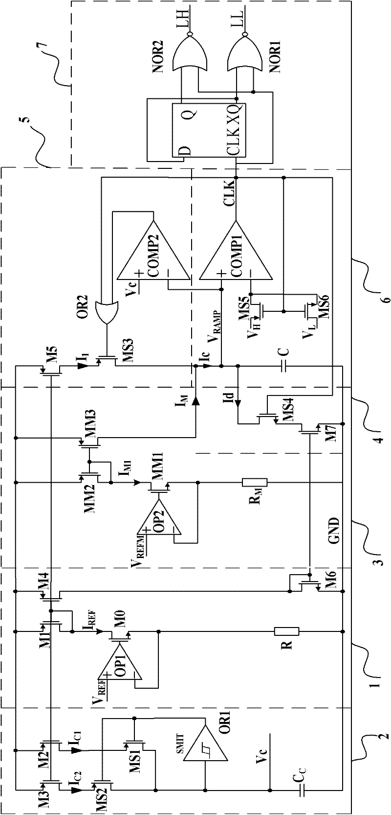
[0032] refer to figure 2, The multi-frequency oscillator of the present invention mainly includes a reference current generation and mirror circuit 1, a control voltage generation circuit 2, a minimum current generation circuit 3, a charge current control circuit 4, a discharge current control circuit 5, an oscillation circuit 6 and a dead zone logic circuit 7. Wherein the reference current generation and the output terminal of the mirror circuit 1 are connected in parallel with the control voltage generation circuit 2, the minimum current generation circuit 3, the charge current control circuit 4 and the discharge current control circuit 5 to provide accurate bias current signals for each circuit; the control voltage The output of the generating circuit 2 is connected to the charging current control circuit 4 to control the charging cu...


PUM


Abstract

The invention discloses a multi-frequency oscillator which has dead time and is applied to an electronic ballast, and mainly solves the problems of no pre-heating, insufficient pre-heating time and short service life of a pre-heating fluorescent lamp. The multi-frequency oscillator comprises a reference current and mirror image circuit (1), a control voltage generation circuit (2), a minimum current generation circuit (3), a discharge current control circuit (4), a charge current control circuit (5), an oscillator circuit (6) and a dead logic circuit (7); an output end of the control voltage generation circuit (2) is connected with the charge current control circuit (5) to generate gradually-changing charge current; the minimum current generation circuit (3) generates minimum charge current; the oscillation circuit (6) generates a time signal with gradually-variable frequency; and an output end of the oscillation circuit (6) is connected with the dead logic circuit (7) to generate a high-end control signal and a low-end control signal which are used for stabilizing the dead time. By the multi-frequency oscillator, the normal operation of the pre-heating fluorescent lamp can be ensured, the service life of the lamp can be prolonged, and the light efficiency is improved.

Description

technical field [0001] The invention belongs to the technical field of electronic circuits, and relates to an analog integrated circuit, in particular to a multi-frequency oscillator, which can be applied to electronic ballasts for preheating fluorescent lamps. Background technique [0002] Multi-frequency oscillators are widely used in electronic ballasts for preheating fluorescent lamps. By changing the oscillation frequency in different time periods, the preheating, ignition and normal lighting of fluorescent lamps can be realized. According to the characteristics of the preheating fluorescent lamp, its normal operation has three stages: 1. When the lamp circuit is at a higher frequency point f ph 2. When the frequency gradually decreases and tends to the natural frequency point f of the LCC series resonant parallel load circuit 0 3. Finally, make the fluorescent lamp work at a constant frequency f run , normally emit light under rated power. [0003] figure 1 It is a...

Claims


Application Information

Patent Timeline
Patent Type & Authority Applications(China)
IPC IPC(8): H05B41/36
Inventor 来新泉叶强聂海英赵永瑞田磊
Owner XIDIAN UNIV
Why Eureka
Try Eureka