
Disc Milling Cutters and Cutting Elements

A technology of cutting elements and disc milling cutters, used in milling cutting inserts, milling cutters, tools of sawing machines, etc., can solve the problems of limited maximum clamping force, blade retraction, large centrifugal force, etc., to reduce harmful vibrations , high cutting thickness, improved durability

Inactive Publication Date: 2011-12-21
LINSINGER MASCHENBAU GES
View PDF2 Cites 13 Cited by
  • Summary
  • Abstract
  • Description
  • Claims
  • Application Information

AI Technical Summary

Problems solved by technology

Due to structural design or material engineering reasons, the maximum clamping force that can be achieved is limited, so especially for disc milling cutters, if large centrifugal forces occur during use, it may cause the insert to retract from the tool holder

Method used


Image

  • Disc Milling Cutters and Cutting Elements
  • Disc Milling Cutters and Cutting Elements

Examples


Embodiment Construction

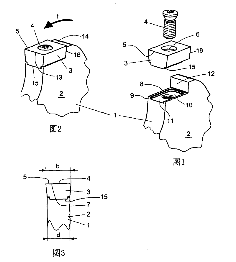
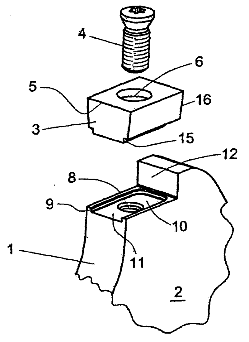
[0025] Figures 1 to 3 A preferred embodiment of the invention, shown in excerpt in , comprises a tool (1) for machining, in particular for high-feed milling and / or sawing, having a disc-shaped Base body (2) and a plurality of replaceable cutting elements (3) arranged in the edge region of the disc-shaped base body (2), just like a carbide milling cutter, and with fixing elements (4) for cutting The element (3) is fastened detachably on the edge region of the disc-shaped base body (2). The cutting element (3) has a substantially prismatic or cuboidal basic shape with at least one cutting edge (5) whose maximum width (b) exceeds the thickness (d) of the disk-shaped base body (2). In the embodiment shown in the figure, the cutting edge width (b) is about 10 mm, the disc thickness is about 8 mm, and the cutting element (3) has at least one through hole (6) for carrying the fixing member (4), wherein all The fastening means in the exemplary embodiment are formed by a fastening s...


PUM


Abstract

The invention relates to a disc milling tool for milling or sawing metal blanks, with a disc-shaped base body (2) at or on its edge region with a plurality of movable Replacement cutting elements (3), such as in particular cemented carbide milling cutters, wherein a seat ( 10), and the design of the cutting element (3) is stress-fitted or form-fitted in abutment contact with the base (10) or against the base (10), or is loaded on it, so that at least this is perpendicular to the plane of the disc The cutting forces acting on the cutting elements (3) are respectively absorbed by the respective bases (10), wherein the bases (10) have a base bearing surface (11) which is defined by a raised edge (9), whereby the raised edge ( 9) and the base (10) form a loading recess open on one side for positively fitting loading of the cutting element (3).

Description

technical field [0001] The invention relates to a disc milling tool for milling or sawing metal blanks, in particular such as metal tubes or bars, with a disc-shaped base and a plurality of blades arranged on the disc-shaped base. Replaceable cutting element in the edge region with fastening means for detachably fixing the cutting element in the edge region of a disc-shaped base body, the invention also relates to a cutting element for use in a disc milling tool element. Background technique [0002] DE 34 25 699 PS discloses such a knife of the same applicant. The cutting tool is used for machining, especially for high-feed milling process, which has a disc-shaped base and a plurality of replaceable cutting elements arranged in the edge region of the disc-shaped base, which is just like hard Alloy milling cutters or indexable inserts with fastening means for detachably fastening the cutting element to the edge region of the disc-shaped base body. In order not to reduce t...

Claims


Application Information

Patent Timeline
IPC IPC(8): B23C5/08B23C5/22B23D61/06
CPCB23C2210/168B23D61/06B23C5/2221B23C5/08B23C2200/161B23C2200/121B23C5/2213
Inventor 汉斯·纳尔
Owner LINSINGER MASCHENBAU GES
Learn More