Radiation tubes and particle accelerators with radiation tubes

A radiant tube and conductor technology, applied in the field of radiant tubes, can solve the problems of increased breakdown possibility, inability to effectively prevent metal ring charging, slow creepage distance flow of charges, etc., and achieve the effect of simple manufacturing

Inactive Publication Date: 2011-12-21
SIEMENS AG
View PDF9 Cites 2 Cited by
  • Summary
  • Abstract
  • Description
  • Claims
  • Application Information

AI Technical Summary

Problems solved by technology

Does not effectively prevent the charging of the metal ring, since the metal ring is embedded in the insulation of the insulating core, and thus the applied charge can only flow out slowly over the creepage distance
Therefore, the operation of the linac with high-speed acceleration pulses leads to an increased probability of breakdown

Method used


Image

  • Radiation tubes and particle accelerators with radiation tubes
  • Radiation tubes and particle accelerators with radiation tubes

Examples


Embodiment Construction

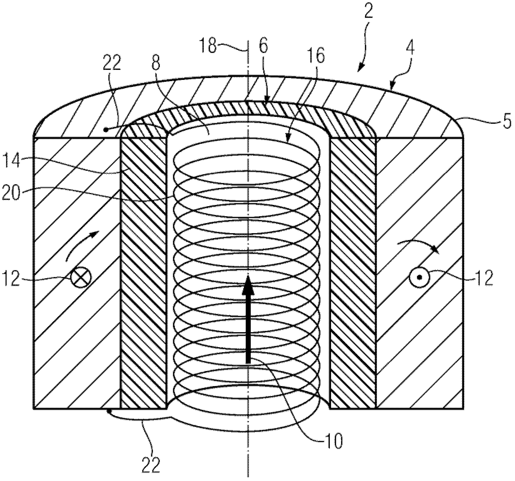
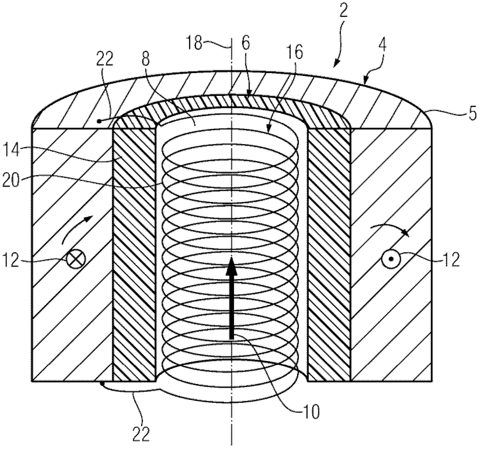
[0027] The particle accelerator 2 is designed, for example, as a linear accelerator, in which the accelerating electric field is supplied by a direct voltage or by a pulsed alternating voltage (cf. Widerrow Linear Accelerator, 1928). However, particle accelerators can also be designed as dielectric wall accelerators.

[0028] The radiation tube 4 is only shown schematically as a hollow cylinder. It comprises a tubular metal casing 5 . However, it is also possible to have accessories, for example a vacuum pump system which is not shown in the figure. The radiant tube 4 houses an insulating core 6 which is likewise hollow cylindrical. The insulating core 6 in turn immediately surrounds the beam-guiding cylindrical hollow volume 8 . A charged particle beam 10 , shown only schematically, is guided and accelerated within the hollow volume 8 .

[0029] Particle Accelerator 2 is based on the principle of electromagnetic induction. The particle accelerator generates a magnetic fi...


PUM


Abstract

A radiant tube (4) for guiding a charged particle stream (10) has a hollow cylindrical isolation core (6) directly encompassing a beam-guiding hollow volume (8). The isolation core (6) is formed from a dielectrically acting carrier substrate (14) and an electrical conductor (16) held therein. The conductor (16) is divided into a plurality of conductor loops (20) completely encompassing the circumference of the isolation core (6) at different axial positions of the isolation core (6). The conductor loops (20) are galvanically connected to each other.

Description

technical field [0001] The invention relates to a radiation tube for guiding a charged particle beam and to a particle accelerator with such a radiation tube. Background technique [0002] Such radiation tubes are designed in particular for particle accelerators for charged particles. A charged particle beam may include, for example, electrons, atomic nuclei, ionized atoms, charged molecules, or charged molecular fragments. The charged particle beam is accelerated in a beam-guiding hollow volume enclosed by a radiation tube. The hollow volume is usually evacuated when the particle accelerator is in operation. For this purpose, a vacuum pump system associated with the radiation tube is usually provided. [0003] The radiation tube, which isolates the hollow volume and charged particle beam from the environment, is electrostatically charged by an accelerating electric field. As the field strength of the electric field increases, the probability of scattered electrons escap...

Claims


Application Information

Patent Timeline
Patent Type & Authority Applications(China)
IPC IPC(8): H05H5/02H05H7/00H05H7/22H01J37/02
CPCH05H9/005H05H7/00H05H7/22H05H5/02
Inventor 奥利弗.海德
Owner SIEMENS AG
Why Eureka
Try Eureka