Manufacturing process of plug-in water dropper used for subsurface drip irrigation

A production process and underground drip irrigation technology, applied in the direction of spraying devices, spraying devices, etc., can solve the problems of affecting production and use effects, complex production process, high production cost, etc., and achieve easy maintenance and repair, good seepage irrigation effect, and manufacturing method simple effect

Inactive Publication Date: 2013-05-15
SHIHEZI UNIVERSITY
View PDF7 Cites 0 Cited by
  • Summary
  • Abstract
  • Description
  • Claims
  • Application Information

AI Technical Summary

Problems solved by technology

The plug-in infiltration irrigation pipe has the advantages of good infiltration irrigation effect, safe and simple and convenient use, but its structure is complicated, and the manufacturing process is complicated, and the production cost is high, which affects the production and use effect

Method used


Image

  • Manufacturing process of plug-in water dropper used for subsurface drip irrigation
  • Manufacturing process of plug-in water dropper used for subsurface drip irrigation
  • Manufacturing process of plug-in water dropper used for subsurface drip irrigation

Examples


Embodiment 1

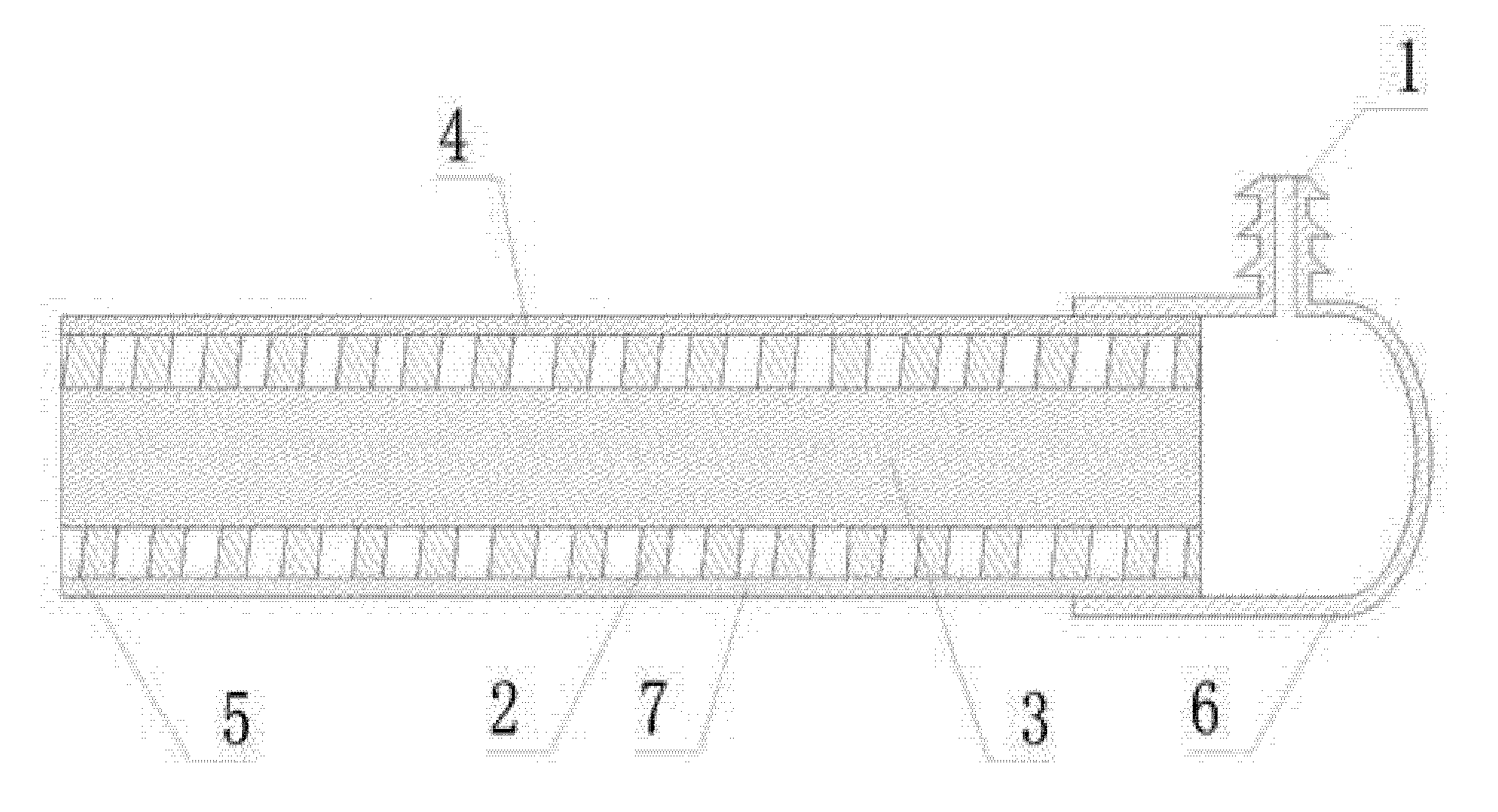
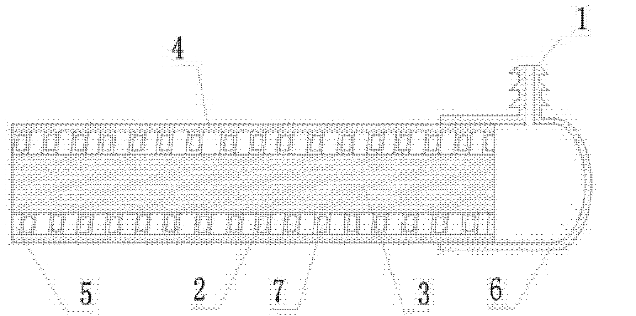
[0033] refer to figure 1 , figure 2 , Figure 4 , is a structural schematic diagram of the implementation of the present invention 1, including a plug-in dripper for underground drip irrigation disclosed by the present invention, comprising a pipe body shell 4, a water inlet connecting pipe 1, the inside of the pipe body shell 4 is a cavity, and the pipe body A solid rod 3 is provided inside the casing 4, and a spiral channel 7 is provided between the solid rod 3 and the tubular casing 4. One end of the spiral channel 7 communicates with the water inlet connecting pipe 1, and the other end opens to form a drip port 5 .

[0034] The water inlet connecting pipe 1 is connected with the pipe body shell 4 through a water inlet cap 6, and the inside of the water inlet cap 6 is a cavity, and the water inlet connecting pipe 1 communicates with the spiral water channel 7 through the cavity.

[0035] The spiral water channel 7 is constituted as follows: a spiral line 2 is provided b...

Embodiment 2

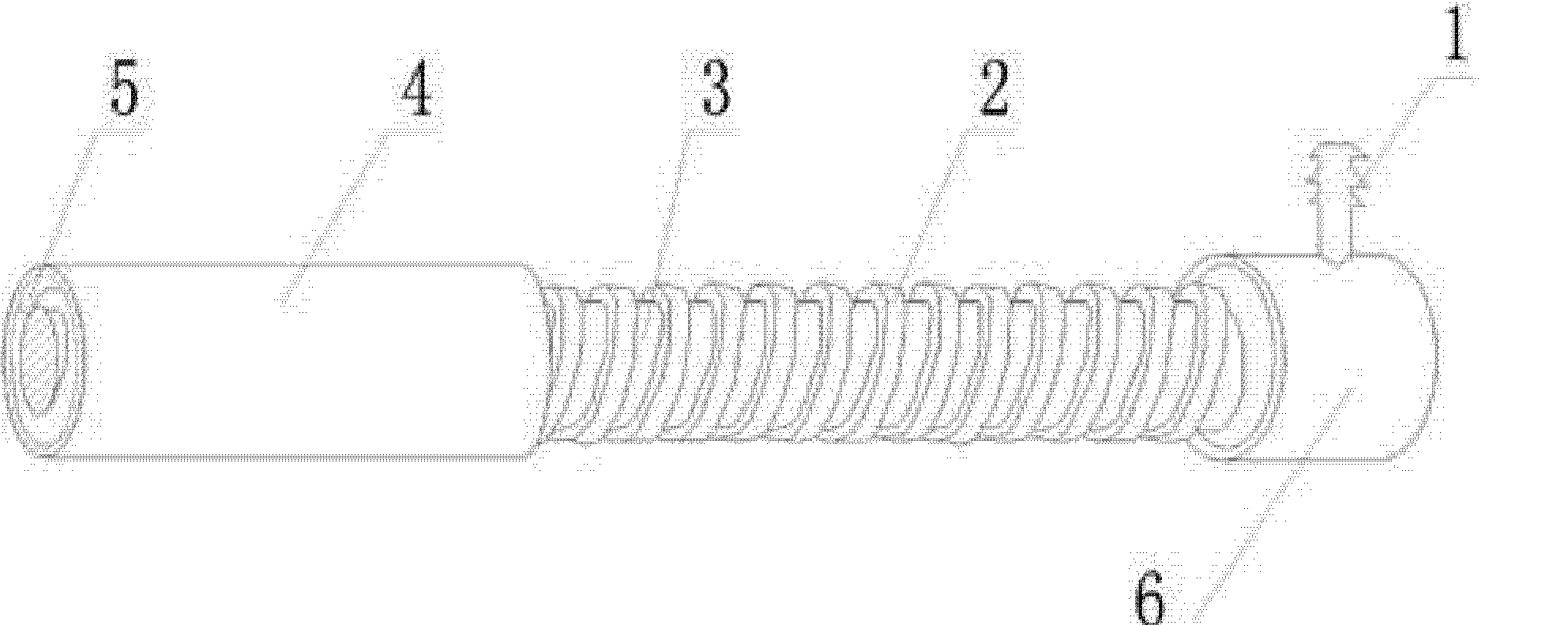
[0048] refer to image 3 , Compared with Embodiment 1, the difference of this embodiment is that the spiral line 2 is a hollow line, the cavity of the hollow line forms a spiral water channel 7, and the cross section of the spiral line 2 is circular.

Embodiment 3

[0050] Compared with Embodiment 1, the difference of this embodiment is that there is no water inlet cap 6 between the water inlet connecting pipe 1 and the pipe shell 4 , and the water inlet connecting pipe 1 directly communicates with the spiral water channel 7 . In the manufacturing process step, one end of the segmented pipe strip is sealed, a hole is drilled in the shell to communicate with the spiral water channel 7, polyvinyl chloride glue is applied, and then the water inlet connecting pipe 1 is inserted to obtain a plug-in drip finished head. The section of the spiral line 2 is triangular.


PUM


Abstract

The invention relates to a device used for subsurface drip irrigation and a manufacturing process thereof. The plug-in water dropper used for the underground drip irrigation comprises a tube case and an inflow connecting pipe, wherein the tube case is internally provided with a solid rod, and a spiral water pipeline is arranged between the solid rod and the tube case. The manufacturing process mainly comprises the following steps: determining a concrete structure of the plug-in water dropper; carrying out extrusion moulding to form a hollow or solid spiral line and a cylinder type solid rod, directly winding the spiral line on the solid rod, and integrating the spiral line with the solid rod by hot seal; winding a casting film producing belt on the outer layer of the spiral line and carrying out the heat seal, and carrying out mutual side pressing and the heat seal while the film belt is wound so as to manufacture a drip irrigation tube; producing an inflow cap finished product for standby application; cutting the drip irrigation tube into sections; and coating glues at one end of the sectioned drip irrigation tube, and inserting the inflow finished product. The plug-in water dropper has simple structure, and is simple and convenient to mount and dismount, easy to maintain and economic and practical, and the manufacturing process of the plug-in water dropper has simple manufacturing method, is convenient to operate, can greatly save cost and is economic and practical.

Description

technical field [0001] The invention relates to a device and a manufacturing process for underground drip irrigation, in particular to a plug-in dripper for underground drip irrigation and a manufacturing process. Background technique [0002] At present, new water-saving irrigation technologies such as sprinkler irrigation and drip irrigation are increasingly used in various fields of agricultural production. A new type of water-saving irrigation technology for fruit trees is often used in tree planting, that is, underground drip irrigation technology. Drip irrigation technology uses plastic pipes to send water to the roots of crops, and then connects a dripper with a special structure buried in the ground to seep water into the roots of crops for irrigation, which has significant water-saving, energy-saving and labor-saving features. Due to the great difference in the structure of the dripper, the working effect is also different. Chinese patent CN2845434 discloses a plug-...

Claims


Application Information

Patent Timeline
Patent Type & Authority Patents(China)
IPC IPC(8): B05B1/22
Inventor 李明思康绍忠姚立民
Owner SHIHEZI UNIVERSITY
Why Eureka
Try Eureka