An automatic capping machine

A capping machine and automatic technology, applied in the direction of hand-held tools, manufacturing tools, etc., can solve the problems of low product qualification rate, low work efficiency, high labor intensity, etc., and achieve low labor intensity, high work efficiency, and high pass rate. Effect

Inactive Publication Date: 2011-12-28
SINO ASIA PLASTIC PACKAGE ZHONGSHAN
View PDF16 Cites 17 Cited by
  • Summary
  • Abstract
  • Description
  • Claims
  • Application Information

AI Technical Summary

Problems solved by technology

In this way, the labor intensity of the operators is very high, the work efficiency is low, and the qualified rate of the products is low.

Method used


Image

  • An automatic capping machine
  • An automatic capping machine
  • An automatic capping machine

Examples


Embodiment Construction

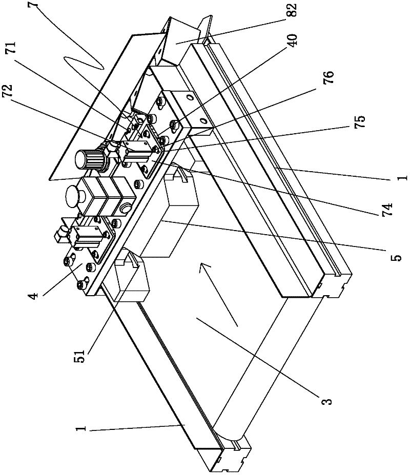
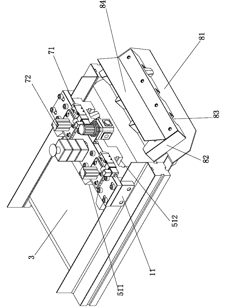
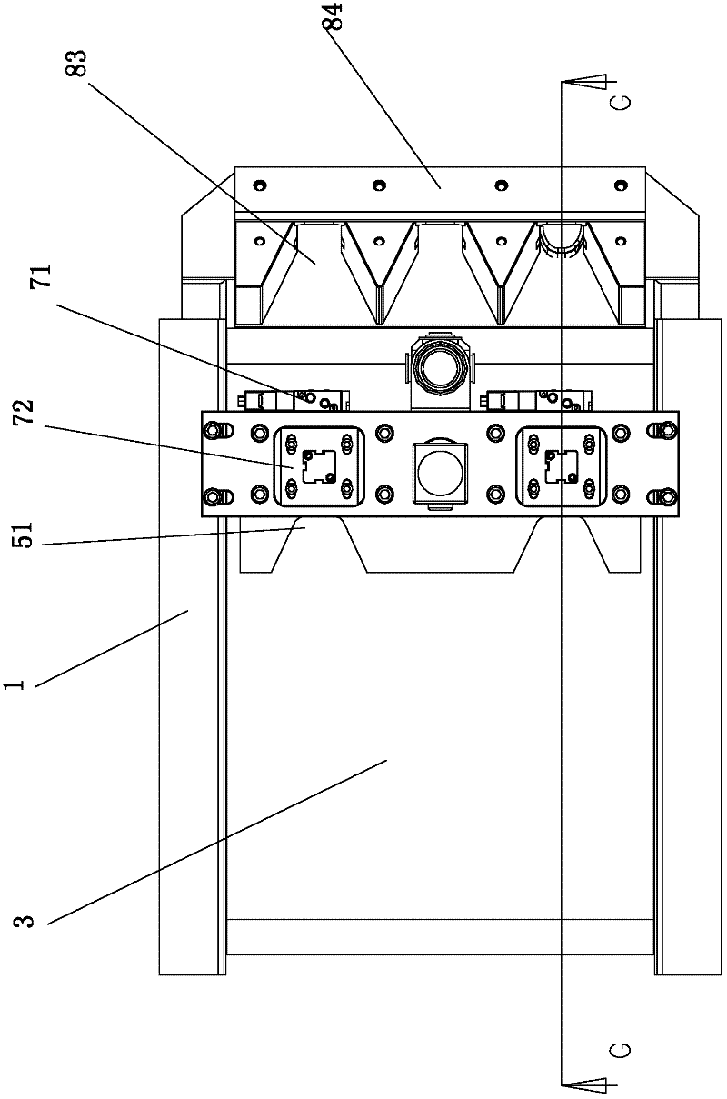
[0021] The present invention is an automatic capping machine, which includes two left and right wing plates 1 and a main controller 2, and a feeding belt 3 is installed between the two wing plates 1, and the feeding belt 3 is controlled by the main controller 2 to rotate to carry out To transport bottle caps, a transverse base plate 4 is fixed on the two wing plates 1. The transverse base plate 4 is located above and close to the feeding belt 3. At the bottom of the transverse base plate 4, there are two bottle caps arranged along the conveying direction of the feeding belt 3. The channel 51 is equipped with a detection device 6 in the bottle cap channel 51. When a bottle cap passes through, the detection device 6 will detect and send the detection signal to the main controller 2. A capping device 7 is provided on the transverse substrate 4. After the main controller 2 receives the signal from the detection device 6 , it immediately controls the capping device 7 to extend downw...


PUM


Abstract

The invention discloses an automatic capping machine, comprising a left wing plate, a right wing plate and a master controller, wherein a feeding belt used for conveying bottle caps under the control the master controller is arranged between the two wing plates; transverse base plates are fixed to the two wing plates; the transverse base plates are arranged above the feeding belt and close to each other; a bottle cap channel along the conveying direction of the feeding belt is arranged on the bottom of each transverse base plate; the bottle cap channel is internally provided with a detection device which is used for detecting the bottle caps and transmitting a detection signal to the master controller; and a transverse base plate is provided with a capping device which extends downward into the bottle cap channel under the control of the master controller and is used for pressing the bottle caps. The invention aims at providing an automatic capping machine with high working efficiency and high yield of extruded products.

Description

[technical field] [0001] The invention relates to an automatic capping machine. [Background technique] [0002] At present, in the bottle cap industry, when the main cap and the secondary cap of each bottle cap are assembled, they are all manually operated. Operator labor intensity is very big like this, and work efficiency is lower, and the qualified rate of product is low. [Content of the invention] [0003] The invention overcomes the disadvantages of the above technologies and provides an automatic capping machine with high working efficiency and high qualified rate of extruded products. [0004] To achieve the above object, the present invention adopts the following technical solutions: [0005] An automatic capping machine, including left and right wing plates and a main controller, a feeding belt controlled by the main controller to transport bottle caps is installed between the two wing plates, and a horizontal base plate is fixed on the two wing plates , the tr...

Claims


Application Information

Patent Timeline
Patent Type & Authority Applications(China)
IPC IPC(8): B25B27/00
Inventor 甘松绍
Owner SINO ASIA PLASTIC PACKAGE ZHONGSHAN
Why Eureka
Try Eureka