Outsourcing multi-cavity steel plate concrete composite shear wall and its construction method

A steel plate concrete and composite shear wall technology, applied in the direction of walls, building components, buildings, etc., can solve the problem of unsatisfactory ductility and other problems, achieve a wide range of applications and development space, good performance, and save materials.

Inactive Publication Date: 2011-12-28
广州容柏生建筑结构设计事务所(普通合伙)
View PDF4 Cites 37 Cited by
  • Summary
  • Abstract
  • Description
  • Claims
  • Application Information

AI Technical Summary

Benefits of technology

This patented technology improves structural strength by making it stronger than previous designs while also being easier to connect or disconnect from existing structures without requiring significant laborious work on site. It simplifies the building's design process and increases efficiency during construction.

Problems solved by technology

This patented technical problem addressed in this patents relates to improving the strength and durability of sheared wall structures made from materials like cement or metal wire rods without compromising their flexibility for use under high tensile stress conditions such as those caused by seismic activity or earthquake events.

Method used


Image

  • Outsourcing multi-cavity steel plate concrete composite shear wall and its construction method
  • Outsourcing multi-cavity steel plate concrete composite shear wall and its construction method
  • Outsourcing multi-cavity steel plate concrete composite shear wall and its construction method

Examples


Embodiment 1

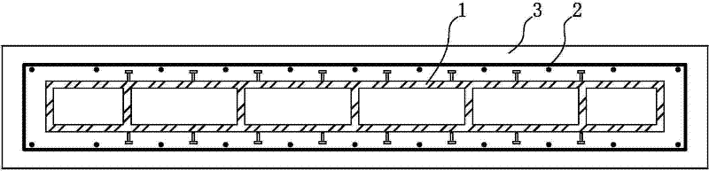
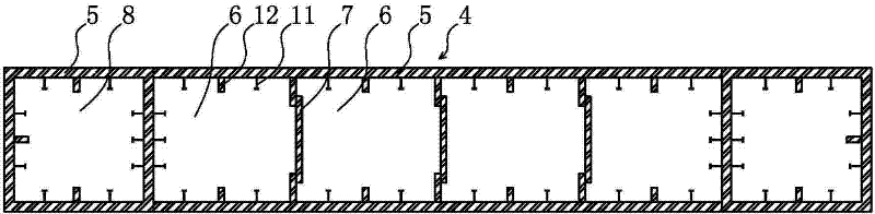
[0028] Such as figure 2 As shown, in the outsourcing multi-cavity steel plate concrete composite shear wall of the present invention, the outer periphery of the wall body 4 is surrounded by steel plates 5, and the interior of the wall body 4 is divided into several interconnected cavities 6. Fill with concrete. Both ends of the wall body 4 are respectively provided with concealed column cavities 8 surrounded by steel plates, and the concealed column cavities are filled with concrete, which is not shown in the figure. The inner side of the steel plate 5 is provided with several studs 11, the studs are perpendicular to the steel plate, the studs can increase the bonding force between the concrete and the steel plate and prevent the steel plate from buckling under pressure. The inner side of the steel plate is also provided with several stiffening ribs 12, the stiffening ribs 12 are perpendicular to the steel plate, and the stiffening ribs can prevent the steel plate from buckl...

Embodiment 2

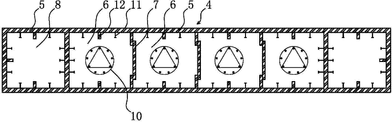
[0031] Such as image 3 As shown, the difference between this embodiment and the first embodiment is that each cavity in the wall is provided with a reinforcement cage 10 respectively. Setting the reinforcement cage is mainly applicable to the situation that the wall thickness is relatively large, and profiled steel or reinforcement can also be placed in the concealed column cavity 8 according to the force requirements.

Embodiment 3

[0033] Such as Figure 4 As shown, the difference between this embodiment and the first embodiment is that the wall is provided with a steel mesh 9, and the steel mesh 9 is distributed in each cavity 6 and connects each cavity. Setting the reinforcement mesh 9 is mainly applicable to the situation where the wall thickness is relatively large, and profiled steel or reinforcing bars can also be placed in the concealed column cavity 8 according to the force requirements.

[0034] The present invention imposes constraints on the concrete in the shear walls. Among them, square concrete-filled steel tube columns are formed in the hidden column cavity at the end; multiple continuous and semi-closed cavities are formed on the wall body by using steel plates on both sides and opposite slabs, which also form constraints on the concrete in them. Thus, the mechanical properties of high-strength concrete, especially the deformation capacity, can be effectively improved.

[0035] The wall...


PUM


Abstract

The invention discloses an outsourcing multi-cavity steel plate concrete composite shear wall and a construction method thereof. The outer periphery of the wall is surrounded by steel plates, and the interior of the wall is divided into several interconnected cavities filled with concrete. During the construction of the present invention, the concealed column cavities at both ends are hoisted to the poured lower shear wall and connected and fixed, and then the wall is hoisted to the poured lower shear wall and connected with the concealed column cavity and the lower shear wall. The walls are respectively connected and fixed, then the reinforcement cage/net is placed in the cavity, and finally concrete is poured in the cavity of the concealed column and the cavity of the wall. The advantages of the present invention are as follows: 1. The structure is reasonable, the performance is good, and the ductility is greatly improved. 2. Give full play to the performance advantages of steel and concrete, save materials and cost. 3. Simple connection with floor steel beams, outrigger trusses and other components, simple and convenient construction process and high efficiency. The invention is suitable for high-rise and super high-rise buildings, and has wide application range and development space.

Description


Claims


Application Information

Patent Timeline
Owner 广州容柏生建筑结构设计事务所(普通合伙)
Why Eureka
Try Eureka