A hydraulic shearing sampling drilling tool

A cutting-type drilling tool technology, which is applied in the fields of geology, petroleum, and ocean exploration, can solve problems such as sampling difficulties, sample disturbance, and drill pipe bending, and achieve the goal of improving sample collection rate, speed of disassembly and assembly, and efficiency Effect

Inactive Publication Date: 2011-12-28
CHINA OILFIELD SERVICES +1
View PDF6 Cites 6 Cited by
  • Summary
  • Abstract
  • Description
  • Claims
  • Application Information

AI Technical Summary

Problems solved by technology

[0003] The conventional sampling method mainly adopts rotary sampling, that is, the drilling equipment drives the drill pipe and sampling drilling tool to rotate, thereby cutting the formation and extracting samples. The sampling tube can be single or double. This method is mainly suitable for hard formations. It is easy to cause disturbance, damage and shedding of samples when used in soft formation conditions, and even empty pipes
[0004] Another method is to use a mechanically pressurized drilling tool. Its working principle is to apply pressure to the drill pipe through the drilling equipment, and then the drill pipe transmits pressure to the sampling drilling tool to press the sampling drilling tool into the soft formation, but this method is easy. It will cause bending or even breaking of the drill pipe, and it can only be used in shallow formations, which is greatly limited in application
[0005] The existing various sampling tools generally have problems such as difficult sampling and low efficiency in soft formation conditions such as oceans and land waters. At the same time, samples are often disturbed during the sampling process, making it difficult to obtain high-quality samples.
Another problem with traditional sampling drilling tools is that it takes a long time to disassemble and assemble the sampling mechanism of the sampling drilling tool and the efficiency is low

Method used


Image

  • A hydraulic shearing sampling drilling tool
  • A hydraulic shearing sampling drilling tool
  • A hydraulic shearing sampling drilling tool

Examples


Embodiment Construction

[0012] The present invention will be further described below in conjunction with the accompanying drawings.

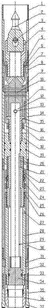
[0013] figure 1 The hydraulic shearing sampling drilling tool shown in the present invention is composed of a sampling outer pipe assembly and a sampling inner pipe assembly arranged in the sampling outer pipe assembly.

[0014] Such as figure 1 As shown, the sampling outer pipe assembly of the present invention includes an upper joint 1, an upper centralizer 8, an outer pipe joint 14, a sampling outer pipe 30, a lower centralizer 32 and a drill bit 37 arranged sequentially from top to bottom. All are tubular, and adjacent pieces are connected to each other by threads. The upper centralizer 8 and the inner wall of the lower centralizer 32 each have a step support surface, a seat ring 7 is arranged on the step support surface in the upper centralizer 8, and a centralizing ring 31 is arranged on the step support surface in the lower centralizer 32 for positioning the f...


PUM


Abstract

The invention relates to a hydraulic shearing type sampling drilling tool which comprises an outer sampling pipe assembly and an inner sampling pipe assembly arranged in the outer sampling pipe assembly, wherein the outer sampling pipe assembly comprises an upper joint, an upper centering device, an outer pipe joint, an outer sampling pipe, a lower centering device and a drill bit which are sequentially arranged from top to bottom; and the inner sampling pipe assembly comprises a suspending system, a guiding system and a press sampling pipe assembly, the guiding system and the press sampling pipe assembly are positioned below the suspending system, and the press sampling pipe assembly can slide up and down in a sealing manner along the inner wall of an outer sampling pipe (30) and the guiding system. The hydraulic shearing type sampling drilling tool provided by the invention has capabilities of effectively solving the sampling problem under conditions of broken grounds such as sea and land water areas and the like and greatly improving quality of samples and increasing sampling efficiency.

Description

technical field [0001] The invention relates to a hydraulic shearing sampling drilling tool, which is used for exploration and sampling drilling in soft formation conditions such as ocean and land waters. It belongs to the technical fields of geology, petroleum and marine exploration. Background technique [0002] At present, with the needs of resource exploration and scientific research, the workload of sampling in soft formations such as oceans and land waters is also increasing. The quality of samples determines the accuracy and scientificity of analysis and research on formations and their components. [0003] The conventional sampling method mainly adopts rotary sampling, that is, the drilling equipment drives the drill pipe and sampling drilling tool to rotate, thereby cutting the formation and extracting samples. The sampling tube can be single or double. This method is mainly suitable for hard formations. It is easy to cause disturbance, damage and shedding of sampl...

Claims


Application Information

Patent Timeline
Patent Type & Authority Applications(China)
IPC IPC(8): E21B49/08
Inventor 赵尔信吴秋云蒋卫炎王明田翁炜蔡家品贾美玲段宝生张建元阮海龙冯美贵欧阳志勇沈立娜
Owner CHINA OILFIELD SERVICES
Why Eureka
Try Eureka