Control method of hydraulic system and control method of concrete pump truck

A technology of a concrete pump truck and a control method, which is applied in the directions of fluid pressure actuation system components, fluid pressure actuation devices, mechanical equipment, etc., can solve the problem of reduced engine load rate, poor energy saving effect, insufficient pumping capacity, etc. problems, to achieve the effect of increasing the load rate and reducing energy consumption

Active Publication Date: 2011-12-28
ZOOMLION HEAVY IND CO LTD
View PDF5 Cites 9 Cited by
  • Summary
  • Abstract
  • Description
  • Claims
  • Application Information

AI Technical Summary

Problems solved by technology

If the distribution unit, stirring cleaning unit and boom unit do not work or are not working at full load during the pumping operation, the load rate of the engine will be reduced, the pumping capacity cannot be fully utilized, the output power of the engine cannot be fully utilized, and the energy saving effect is insufficient. good

Method used


Image

  • Control method of hydraulic system and control method of concrete pump truck
  • Control method of hydraulic system and control method of concrete pump truck

Examples


Embodiment Construction

[0032] Terminology Explanation

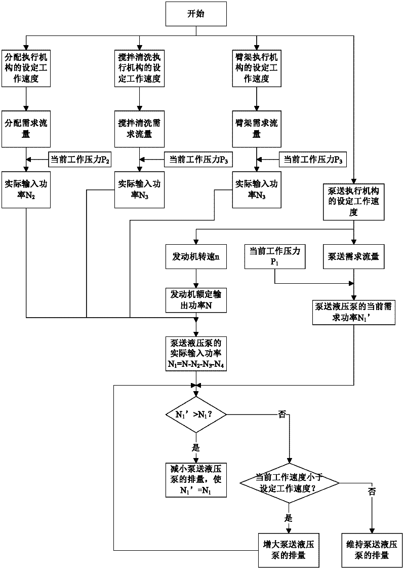
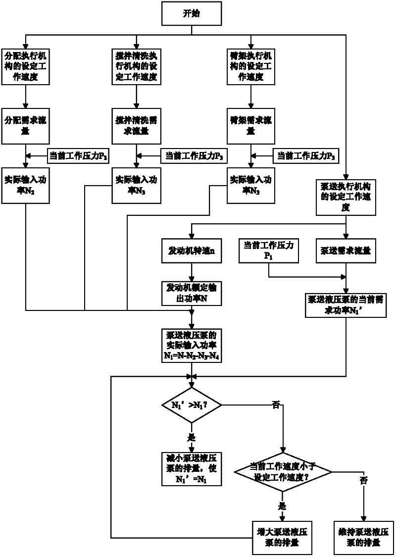
[0033] The set working speed of the actuator: the expected working speed of the actuator set by the staff for a certain working environment and work requirements;

[0034] The current demand power of the variable pump N 1 ’: Determined according to the set working speed and current working pressure of the variable pump;

[0035] The actual input power of the variable pump N 1 : The rated output power N of the prime mover (such as an engine) minus the actual input power N of other hydraulic pumps 2 , N 3 ..., ie N 1 =(N-N 2 -N 3 ...).

[0036] The working principle and working process of the present invention will be described in detail below.

[0037] The present invention firstly discloses a control method of a hydraulic system, the hydraulic system includes a plurality of hydraulic pumps driven by a prime mover, and each hydraulic pump drives a corresponding actuator, and a first variable pump is included in the plurality of hydraulic...


PUM


Abstract

The invention discloses a control method of a hydraulic system, the hydraulic system comprises multiple hydraulic pumps driven by a prime motor, and each hydraulic pump drives a corresponding actuating mechanism; a first variable displacement pump in the multiple hydraulic pumps drives a first actuating mechanisms; according to the set working speed of the first actuating mechanism and the maximum displacement of the first variable displacement pump, the working speed of the prime motor is determined; according to the set working speed and the current working pressure of the first actuating mechanism, the current demanded power of the first variable displacement pump is determined; the actual input power N1 of the first variable displacement pump is equal to the difference value obtained by subtracting the actual input power of other hydraulic pumps from the output rating of the prime motor. According to the control method, the displacement of the first variable displacement pump is reduced when the current demanded power of the first variable displacement pump is higher than the actual input power, so that the current demanded power of the first variable displacement pump is equal to the actual input power N1. The invention also provides a control method of a concrete pump truck. By the adoption of the invention, the work efficiency can be improved, the load factor of the prime motor can be improved, and the effects of energy conservation and consumption reduction can be achieved.

Description

technical field [0001] The invention relates to the control field of a hydraulic system, in particular to a control method of a hydraulic system and a control method of a concrete pump truck. Background technique [0002] In some hydraulic systems, it is often the case that a prime mover (such as an engine) drives multiple hydraulic pumps through transmission devices such as a transfer case, and each hydraulic pump drives a corresponding actuator to act through hydraulic transmission. [0003] For example, in terms of a concrete pump truck, the hydraulic system of the concrete pump truck usually includes a plurality of hydraulic units, such as a pumping unit, a distributing unit, a stirring and cleaning unit, and a boom unit. The pumping unit includes a pumping hydraulic pump and a pumping actuator for pumping concrete; the distribution unit includes a distribution hydraulic pump and a distribution actuator for the distribution of concrete; the mixing and cleaning unit inclu...

Claims


Application Information

Patent Timeline
Patent Type & Authority Applications(China)
IPC IPC(8): F15B21/00
Inventor 万梁陈祺王佳茜高荣芝
Owner ZOOMLION HEAVY IND CO LTD
Why Eureka
Try Eureka