Double-channel differential polarizing interference imaging spectrometer

An interferometric imaging, dual-channel technology, applied in interferometric spectroscopy, optics, instruments, etc., can solve problems such as insufficient characterization of target scattering spectral information, difficult calibration, and disturbance of rotating polarizers, to increase spectral detection capabilities and increase acquisition. Ability to avoid the effect of image changes

Active Publication Date: 2014-08-06
XI AN JIAOTONG UNIV
View PDF6 Cites 1 Cited by
  • Summary
  • Abstract
  • Description
  • Claims
  • Application Information

AI Technical Summary

Problems solved by technology

However, since the polarization direction of the front polarizer in this system is fixed, only the spectral information of the polarization component in the direction of the polarizer can be obtained, but the spectral information of the polarization component perpendicular to it cannot be obtained, which belongs to the single-channel polarization spectrometer
U.S. Patent (Patent No. 6,177,984B1) discloses a technology that uses a rotating polarizer to obtain orthogonally polarized images of epithelial tissue; since the two images are acquired sequentially, if the target changes rapidly, the content of the two images will change. different; and the rotating polarizer will introduce disturbance, which is not easy to calibrate; more importantly, the system cannot obtain spectral information
French scholars have reported a dual-channel differential polarization imager without rotating components, which can quickly obtain the polarization images of the parallel and vertical components of the target. Unfortunately, the system also cannot obtain the spectral information of the target.
[0003] U.S. Patent (Patent No.: 2002 / 0171831) discloses a differential polarization spectroscopy technique for measuring tissue backscattering spectra. The system uses a combination of two linear polarizers and a dual-channel dispersive spectrometer to simultaneously obtain the orthogonal polarization of its target. The spectrum of the component; but the system cannot obtain the image information of the target; and the response arrays of the two channels of the dispersive spectrometer are different; the flux of the spectrometer is limited by the slit, and the detection sensitivity is low; because the two polarizers are placed orthogonally in front of the spectrometer, so Polarization effects of dispersive elements need to be considered
Subsequently, American scholars proposed to use a combination of rotating polarizers and single-channel dispersive spectrometers to achieve this, but the system also cannot obtain image information; and because the spectral information is acquired sequentially, rapid changes in the target will cause spatial misalignment, making it difficult to calibrate; In addition, the rotating polarizer introduces disturbances, which make it difficult to precisely calibrate
In order to obtain the target image at the same time and avoid the limitation of the dispersive spectrometer, American scholars reported a combination of a rotating filter wheel and a rotating polarizer to obtain the polarization difference spectral image of the target, but the number of spectral channels of the filter wheel is too small, The scattering spectral information of the target cannot be fully described
In order to increase the number of spectral channels and reduce the number of rotating parts, American scholars proposed to use liquid crystal tuning filters instead of rotating filter wheels; however, the optical efficiency of liquid crystal tuning filters is inversely proportional to the number of spectral channels, and the spectral range is narrow

Method used


Image

  • Double-channel differential polarizing interference imaging spectrometer
  • Double-channel differential polarizing interference imaging spectrometer
  • Double-channel differential polarizing interference imaging spectrometer

Examples


Embodiment Construction

[0020] The present invention will be further described below in conjunction with the accompanying drawings, in order to illustrate the structural features, technical performance and functional characteristics of the present invention, but not to limit the scope of the present invention.

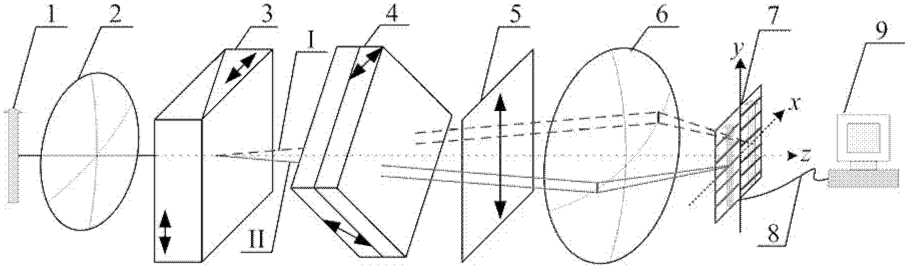
[0021] Please refer to figure 1 A dual-channel differential polarization interference imaging spectrometer according to the present invention consists of a collimator lens 2, a Wollaston prism 3, a Savall polarizer 4, a linear polarizer 5, an imaging lens 6, The area array detector 7, the connecting wire 8 and the computer processing system 9 are composed of: the main section of the Wollaston prism 3 and the Savall polarizer 4 form an angle of 45°; the polarization direction of the linear polarizer 5 is parallel to the Wollaston The main section of the prism 3; the area array detector 7 is placed on the focal plane of the imaging lens 6; the area array detector 7 is connected to the computer ...


PUM


Abstract

The invention relates to a double-channel differential polarizing interference imaging spectrometer, which comprises a collimating lens, a Wollaston prism, a Savart polarizer, a linear polarizer, an imaging lens, a plane array detector, a connecting lead and a computer processing system, wherein after light emitted by a target passes through the double-channel differential polarizing interference imaging spectrometer, interference images of a parallel component and a vertical component of the target can be acquired by using the plane array detector; the interference images are input to the computer processing system through the connecting lead, and Fourier transformation and image fusion processing are respectively performed on the two interference images, so that spectral images of the parallel component and the vertical component of the target can be inversed; the difference of the two spectral images is a differential polarizing spectral image of the target; and the ratio of the difference of the two spectral images to the sum of the two spectral images is a linear polarizing spectral image of the target. The spectrometer has the advantages of simple and compact structure, high sampling precision, good stability, no rotary component, and capability of acquiring the differential polarizing spectral image and the linear polarizing spectral image of the target.

Description

technical field [0001] The invention belongs to the technical field of optical image processing instruments, in particular to a structure of a dual-channel differential polarization interference imaging spectrometer. Background technique [0002] Polarization and spectral information are two important information in the field of remote sensing. Polarization can provide high-contrast shape information of the target, while spectrum can provide attribute information of the target. Differential polarization imaging spectroscopy technology is a technology to simultaneously obtain the spectral image of the parallel and vertical polarization components of the target. The difference between the two components is a high-contrast differential polarization spectral image. The ratio of the difference between the two components and the sum of the two components is Target degree of linear polarization. There are many kinds of remote sensing instruments to obtain target polarization and s...

Claims


Application Information

Patent Timeline
Patent Type & Authority Patents(China)
IPC IPC(8): G01J3/45G02B27/28
Inventor 张淳民穆廷魁高宏文任文艺代海山
Owner XI AN JIAOTONG UNIV
Why Eureka
Try Eureka