Image-Forming Lens, and Imaging Apparatus and Information Device Using the Image-Forming Lens

An imaging lens and image technology, applied in the field of imaging lenses, can solve problems such as insufficient miniaturization

Active Publication Date: 2011-12-28
RICOH KK
View PDF8 Cites 34 Cited by
  • Summary
  • Abstract
  • Description
  • Claims
  • Application Information

AI Technical Summary

Problems solved by technology

But the overall length of the lens is greater than six times the maximum image height
Therefore, it is not enough for miniaturization

Method used


Image

  • Image-Forming Lens, and Imaging Apparatus and Information Device Using the Image-Forming Lens
  • Image-Forming Lens, and Imaging Apparatus and Information Device Using the Image-Forming Lens
  • Image-Forming Lens, and Imaging Apparatus and Information Device Using the Image-Forming Lens

Examples


Embodiment 1

[0158] Next, specific examples are explained based on the embodiments of the present invention as described above.

[0159] Embodiments 1 to 6 below are examples of specific structures constituted by specific numerical examples of the imaging lens according to the present invention. And Embodiment 7 is a specific example of an imaging device or an information device according to an embodiment of the present invention, which uses the lens unit with a zoom lens described in Embodiments 1 to 6 as an imaging optical system.

[0160] Embodiments 1 to 6 describe the structure and specific numerical examples of each imaging lens.

[0161] In each of Examples 1 to 6, the maximum image height was 14.2 mm.

[0162] In Embodiments 1 to 6, as an optical element of a parallel plate placed on the image plane side of the second lens group, an optical filter such as an optical low-pass filter, an infrared cut filter, etc., or a CMOS (complementary A cover glass (sealing glass) or the like o...

Embodiment 2

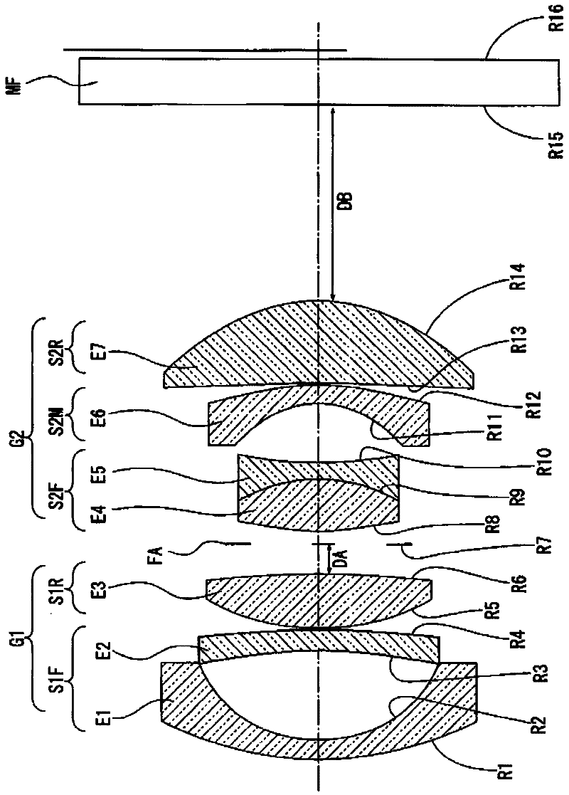
[0266] Figure 4 is a schematic vertical cross-sectional view showing the composition of the optical system of the imaging lens according to Embodiment 2 of the present invention.

[0267] Figure 4 The illustrated imaging lens has a first lens E1, a second lens E2, a third lens E3, a fourth lens E4, a fifth lens E5, a sixth lens E6, a seventh lens E7, an aperture FA, and a filter FA.

[0268] In this case, the first lens E1, the second lens E2, and the third lens E3 constitute a first lens group G1, which is placed on the object side of the aperture FA. The fourth lens E4, fifth lens E5, sixth lens E6, and seventh lens E7 constitute a second lens group G2, which is placed on the image plane (image) side of the aperture FA. Each lens group is supported by a support frame or the like common to each group, and in the case of focusing or the like, each lens group moves integrally.

[0269] In this case, the aperture FA moves integrally with the first lens group G1.

[0270] e...

Embodiment 3

[0342] Figure 7 is a schematic vertical cross-sectional view showing the composition of the optical system of the imaging lens according to Embodiment 3 of the present invention.

[0343] Figure 7 The imaging lens shown has a first lens E1, a second lens E2, a third lens E3, a fourth lens E4, a fifth lens E5, a sixth lens E6, a seventh lens E7, an eighth lens E8, an aperture FA and a filter. Optical device MF.

[0344] The first lens E1, the second lens E2, the third lens E3, and the fourth lens E4 constitute a first lens group G1, which is placed on the object side of the aperture FA. The fifth lens E5, sixth lens E6, seventh lens E7, and eighth lens E8 constitute a second lens group G2, which is placed on the image plane (image) side of the aperture FA. Each lens group is supported by a support frame or the like common to each group, and in the case of focusing or the like, each lens group moves integrally.

[0345] In this case, the aperture FA moves integrally with t...


PUM


Abstract

An image-forming lens comprising, from an object side to an image side in order: a first lens group; an aperture; and a second lens group with a positive refractive power, the first lens group including, from the object side in order: a first F lens group with a negative refractive power; and a first R lens group with a positive refractive power, the first F lens group including, from the object side in order: a first negative lens which has a surface on the image side having a large curvature; and a second negative lens which has a surface on the object side having a large curvature, and the first R lens group including: any one of a positive lens and a cemented lens with a positive refractive power as a whole, wherein a distance from a surface on a most object side of the first lens group to an image plane in a state of focusing on an infinity object: L, and a maximum image height:; Y' satisfy Conditional expression 1:2.8<L / Y'<4.3.

Description

technical field [0001] The present invention relates to an imaging lens that forms an image of a photographed object so as to image a still image or a moving image, and to an imaging device and an information device having an imaging function using the imaging lens, such as a portable information terminal device and the like. The imaging lens can be used in a silver halide imaging device using a silver halide film, especially, the imaging device is suitable for an imaging device using an electronic imaging device, such as a digital camera, a digital video imaging device, and the like. Background technique [0002] As the market for so-called digital cameras has become larger, demands for digital cameras from users have changed. [0003] Among such digital cameras, a category of small imaging devices with high photo quality is attracting users' attention, in which a relatively large image sensor with a diagonal length of about 20mm to 45mm and a high-performance single focal ...

Claims


Application Information

Patent Timeline
Patent Type & Authority Applications(China)
IPC IPC(8): G02B13/04G02B13/18H04N5/225
CPCG02B9/64G02B13/04G02B13/0015G02B9/62G02B13/0045G02B13/006G02B27/0025
Inventor 大桥和泰窪田高士
Owner RICOH KK
Why Eureka
Try Eureka