Magnetic force coupling adjustable transmission gear box

A magnetic coupling and transmission technology, applied in electrical components, electromechanical devices, electromechanical transmission devices, etc., can solve the problems of poor economy, high maintenance cost, complicated manufacturing process, etc., and achieve the effect of improved safety, convenient operation and compact size

Inactive Publication Date: 2013-03-20
SHANGHAI POTEVIO
View PDF4 Cites 4 Cited by
  • Summary
  • Abstract
  • Description
  • Claims
  • Application Information

AI Technical Summary

Problems solved by technology

[0003] The general characteristics of mechanical transmissions are: complex structure, large volume, complicated manufacturing process, high manufacturing cost, large investment scale, large fuel consumption, relatively poor economy, complex mechanism, difficult repair, high maintenance cost, and the shifting performance is lower than that of fluid. The power automatic transmission is poor, and it is not as good as CVT. The frustration, especially the low-level frustration is obvious. The power needs to be cut off during the shifting process, which also has a certain impact on vehicle safety.
Belt-type transmission has a relatively short service life and high maintenance costs

Method used


Image

  • Magnetic force coupling adjustable transmission gear box
  • Magnetic force coupling adjustable transmission gear box
  • Magnetic force coupling adjustable transmission gear box

Examples


Embodiment Construction

[0035] The structure of the present invention will be further described in detail below in conjunction with the accompanying drawings.

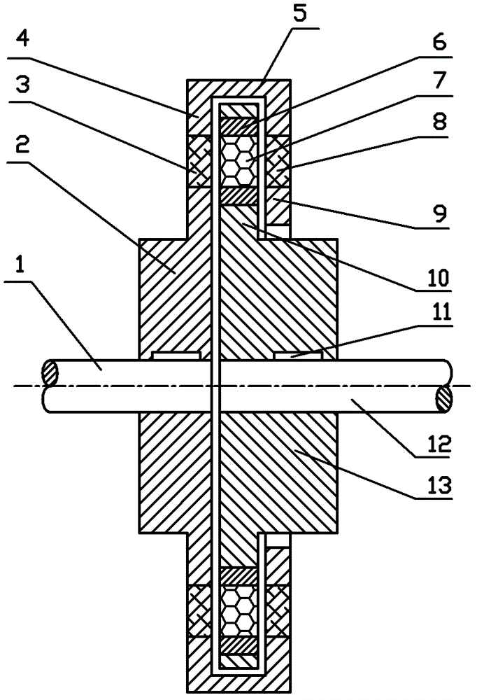
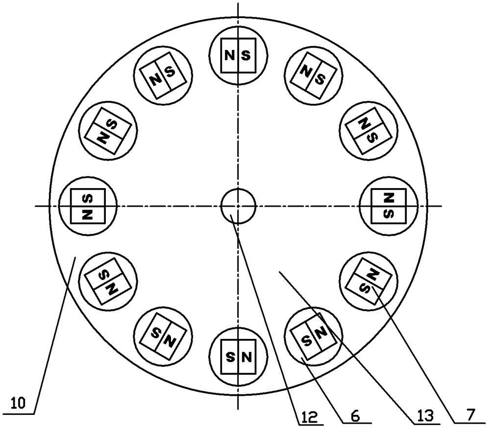
[0036]A magnetically coupled adjustable transmission, in which a conductor disk hub 2 is fixedly connected to the shaft end of the input shaft 1, a circular 1# conductor disk 4 is connected to the conductor disk hub 2, and the 1# conductor disk 4 is embedded or attached on the surface A circle of metal 1# conductor ring 3 is coaxial with the input shaft 1 on the outer edge of the 1# conductor disk 4, and extends a section of air gap spacer pad 5 toward the output shaft 12, and connects a 2# conductor disk 9, The 2# conductor disk 9 is parallel to the 1# conductor disk 4, and a circle of metal 2# conductor ring 8 is embedded or attached on the surface of the 2# conductor disk 9. The size of the 1# conductor ring 3 and the 2# conductor ring 8 are the same, and the positions correspond to ;

[0037] A magnetic disk hub 13 is fixedly connected t...


PUM


Abstract

The invention relates to a speed changer structure and provides a magnetic force coupling adjustable transmission gear box. The transmission gear box is characterized in that: an input shaft (1) is fixedly connected with a 1# conductor disc (4) which is embedded with or attached with a 1# conductor ring (3). An air gap range extension pad (5) connects with a 2# conductor disc (9) and a 2# conductor ring (8). An output shaft (12) is fixedly connected with a magnetic force disc (10). On same circumference of the magnetic force disc (10), a plurality of rotatable rotation round blocks (6) are embedded, and two close permanent magnets (7) with different polarities are placed into each rotation round block (6). S / N polarities of all permanent magnets (7) are in central symmetry with a center of circle of the magnetic force disc (10). The magnetic force disc (10) of the output shaft (12) is positioned between the 1# conductor disc (4) and the 2# conductor disc (9) of the input shaft (1), and axial clearance is existed between the two conductor discs. The rotation round blocks (6) can be in synchronization rotation manually or automatically on the magnetic force disc (10). The conductor ring and the permanent magnet are in corresponding arrangement, torsional force of eddy-current coupling realizes power transmission, angles of the rotatable rotation round blocks are changed, transmission torque is changed, and a purpose of changing load rotating speed is realized.

Description

technical field [0001] The invention relates to a transmission structure, in particular to a device for speed regulation and speed change using the principle of magnetic force coupling. Background technique [0002] A transmission gear box is a device that changes the speed or traction of machines such as machine tools, automobiles, and tractors. It consists of many gears with different diameters. It is usually installed between the driving shaft and the driven shaft of the engine. The transmission is a gear transmission device that can change the transmission ratio of the output shaft and the input shaft in fixed or stepwise steps, also known as a gearbox. The speed changer is composed of a transmission mechanism and a speed change mechanism, which can be made into a separate speed change mechanism or combined with the transmission mechanism in the same housing. The transmission mechanism is mostly driven by ordinary gears, and some are driven by planetary gears. The spee...

Claims


Application Information

Patent Timeline
Patent Type & Authority Patents(China)
IPC IPC(8): H02K51/00
Inventor 王允强郑迪姚志文华敏袁吾均
Owner SHANGHAI POTEVIO
Why Eureka
Try Eureka