A led dimming circuit suitable for thyristor dimmer

A dimmer and LED driver technology, applied in the field of general lighting, can solve the problems of light-emitting jitter, imperfect use effect, high cost, etc., and achieve the effect of reducing production and debugging costs, improving parameter consistency, and simple circuit

Inactive Publication Date: 2011-12-28
缪仙荣
View PDF3 Cites 54 Cited by
  • Summary
  • Abstract
  • Description
  • Claims
  • Application Information

AI Technical Summary

Problems solved by technology

Since the incandescent lamp is a pure resistance, but the LED lamp is not a pure resistance, when it is directly replaced and then dimmed, it is easy to cause the flickering and jitter of the LED lamp
[0005] 2. Many LED driver chip manufacturers have launched chips that can be equipped with thyristor dimmers, but the use effect is not perfect. With some thyristor dimmers, the light can be adjusted normally, and with another thyristor distribution The dimmer is flickering, not compatible with all types of front-cutting and trailing-cutting dimmers
[0006] 3. These dimmable chips have complex circuits, difficult production and debugging, and high costs, which have become an obstacle for LED lamps to replace incandescent lamps

Method used


Image

  • A led dimming circuit suitable for thyristor dimmer
  • A led dimming circuit suitable for thyristor dimmer
  • A led dimming circuit suitable for thyristor dimmer

Examples


Embodiment Construction

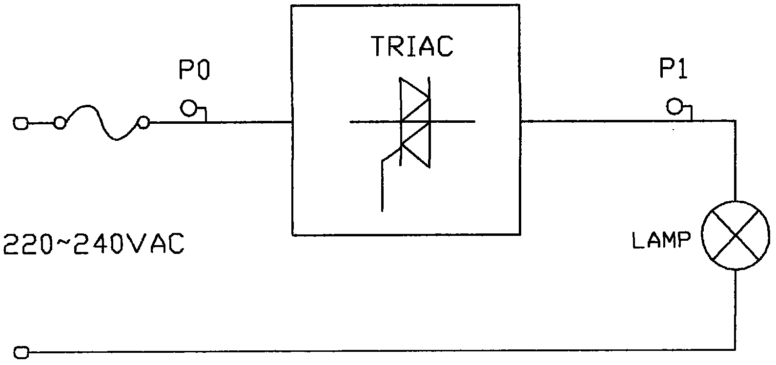
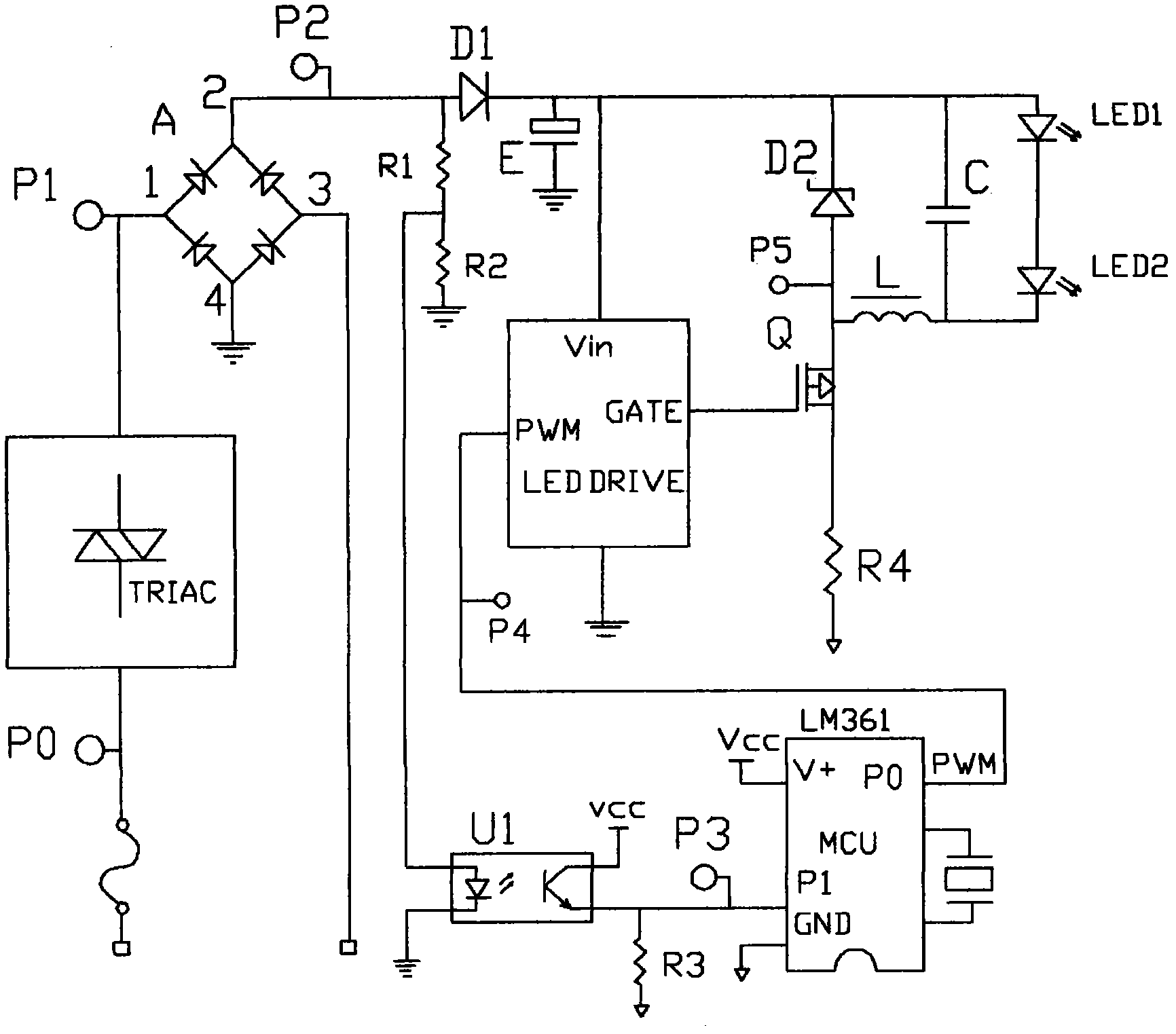
[0017] Example: see Figures 1 to 4 As shown, an LED dimming circuit suitable for thyristor dimmer, 50 / 60Hz AC sine wave waveform is chopped by triac TRIAC, rectified by bridge rectifier circuit A, and taken out by isolation circuit U1 The chopping waveform is sent to the single-chip control unit MCU, and the single-chip control unit MCU outputs the PWM waveform to the LED driver chip LEDDRIVE, and the LED driver chip LEDDRIVE drives the light-emitting diodes (LED1, LED2) to emit light.

[0018] The frequency of the PWM waveform is 3 to 6 times the frequency of the output waveform rectified by the bridge rectifier circuit A.

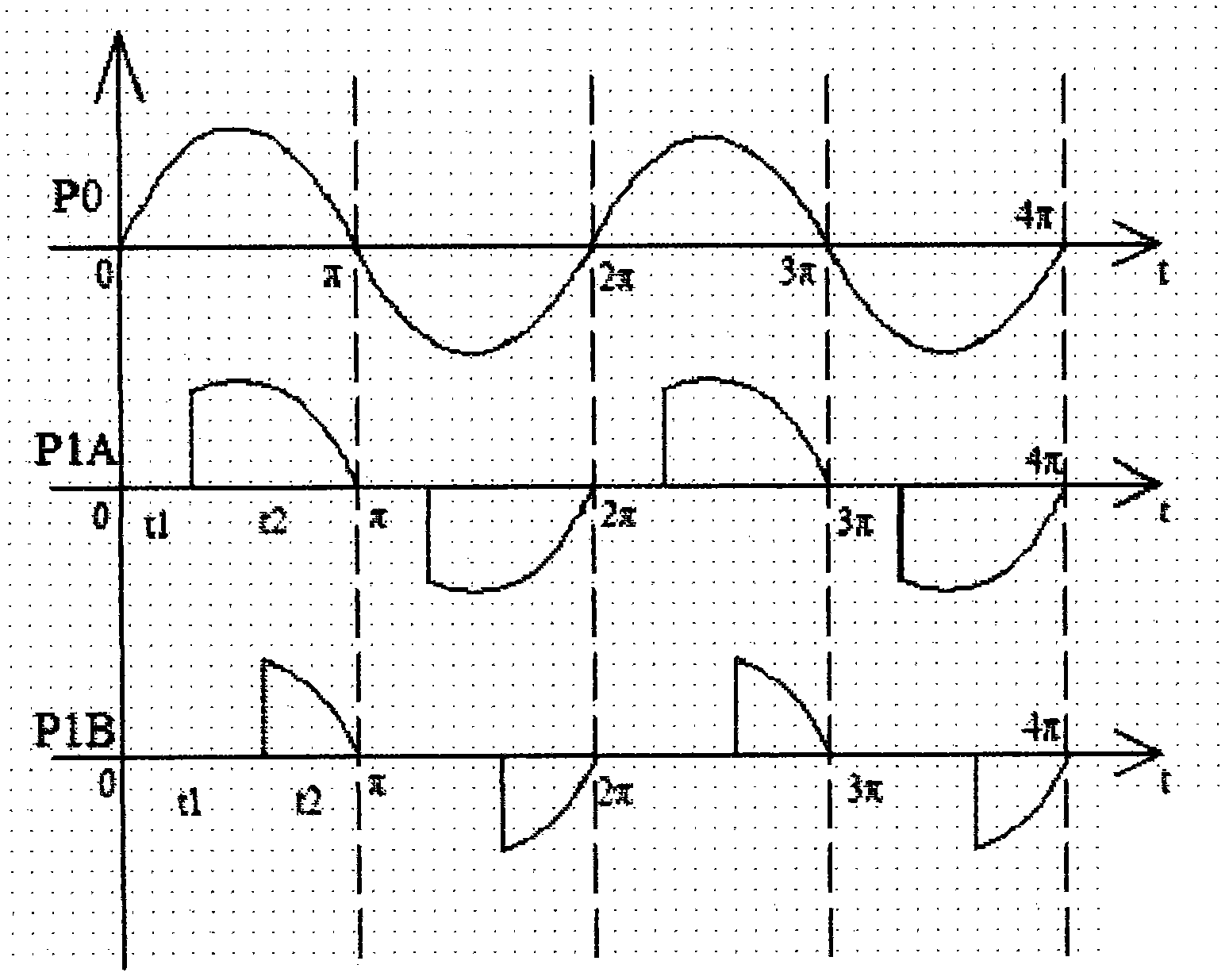
[0019] How it works: combined figure 1 Schematic circuit diagram of a TRIAC dimmer, in figure 2 In the schematic diagram of the waveform of the thyristor dimmer shown: P0 is the input 50Hz AC sine wave waveform, the half cycle is 10ms, and one cycle is 20ms. P1A and P1B are the thyristor chopping waveforms, and the knobs of the thyristor dimmer can b...


PUM


Abstract

An LED dimming circuit suitable for thyristor dimmers, 50/60Hz AC sine wave waveforms are chopped by a triac (TRIAC), rectified by a bridge rectifier circuit (A), and separated by an isolation circuit ( U1) Take out the chopping waveform and send it to the single-chip control unit (MCU), the single-chip control unit (MCU) outputs the PWM waveform to the LED driver chip (LEDDRIVE), and the LED driver chip (LEDDRIVE) drives the light-emitting diodes (LED1, LED2) to emit light. It makes the LED lamp directly replace the incandescent lamp with the same perfect dimming effect, and the circuit is simple and the cost is low, which overcomes an important obstacle for the LED lamp to replace the incandescent lamp.

Description

Technical field: [0001] The invention relates to an LED dimming circuit suitable for a thyristor dimmer, which belongs to the application field of optoelectronic technology and is applied to general lighting. Background technique: [0002] Dimming not only saves energy, but also is necessary for high-quality lighting to meet the lighting needs of different scenes. As a dimming solution for incandescent lamps, SCR dimmers are economical, convenient, and widely used, and the dimming effect is perfect. [0003] At present, due to energy efficiency and environmental protection reasons, countries around the world have legislated to gradually phase out and ban incandescent lamps. The protagonists of lighting are energy-saving lamps and LED lamps. Moreover, because LED lamps have no mercury, no infrared radiation and ultraviolet radiation, they are more efficient, energy-saving and longer life. More environmentally friendly, LED lights are clearly the mainstream of future lighting...

Claims


Application Information

Patent Timeline
Patent Type & Authority Applications(China)
IPC IPC(8): H05B37/02
Inventor 缪仙荣
Owner 缪仙荣
Why Eureka
Try Eureka