Braking energy recovery system for vehicles and vehicles equipped with the system

一种能量回收、制动系统的技术,应用在高效的车辆充电、通用动力装置的多个不同原动机的布置、制动器等方向,能够解决限制、使用复杂等问题,达到构造简单的效果

Active Publication Date: 2011-12-28
14156048 CANADIAN CO
View PDF6 Cites 37 Cited by
  • Summary
  • Abstract
  • Description
  • Claims
  • Application Information

AI Technical Summary

Problems solved by technology

However, the reclamation system requires the use of complex variable transmissions rather than standard transmissions, which limits the potential for retrofitting existing vehicles using the reclamation system

Method used


Image

  • Braking energy recovery system for vehicles and vehicles equipped with the system
  • Braking energy recovery system for vehicles and vehicles equipped with the system
  • Braking energy recovery system for vehicles and vehicles equipped with the system

Examples


Embodiment Construction

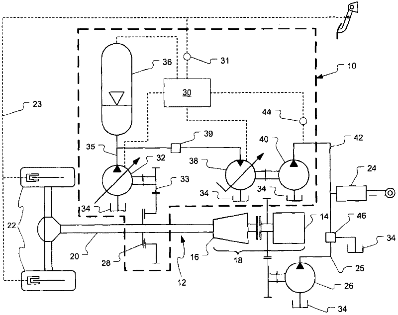
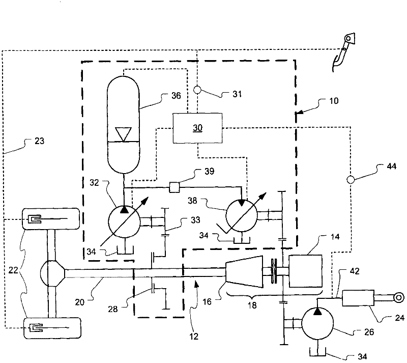
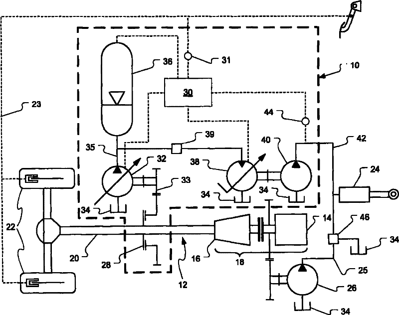
[0018] The present invention relates to a braking energy recovery system which can be installed as standard equipment on new vehicles or as a retrofit to existing vehicles. Through the use of variable displacement hydraulic pumps and motors, the recovered energy can be adjusted according to braking demand and the stored energy can be adjusted according to the power demand from auxiliary systems. Furthermore, in one embodiment of the invention, the brake energy recovery system can also be used to boost the vehicle during acceleration.

[0019] see now figure 1 , which schematically depicts the braking energy recovery system 10 of the present invention. For better understanding, the brake energy recovery system 10 is shown mounted on a powertrain 12 of a vehicle. figure 1 The components of powertrain 12 shown in are: internal combustion engine 14 and transmission 16 , which together form an engine-transmission assembly 18 ; and propshaft 20 , which connects a wheel set 22 to t...


PUM


Abstract

A braking energy recovery system adapted for use on a vehicle and a vehicle having such a system installed. The vehicle has an engine-transmission assembly, a driveshaft, a braking system and an auxiliary system. The energy recovery system comprises a first pump, a hydraulic accumulator and a hydraulic motor. The first pump is a variable displacement hydraulic pump. The hydraulic accumulator is connected to the first pump and is operative to store hydraulic fluid under pressure. The hydraulic motor is hydraulically connected to the accumulator to receive hydraulic fluid. The motor is adapted to drive a second hydraulic pump, which is hydraulically connected to the auxiliary system, using hydraulic energy stored in the accumulator.

Description

technical field [0001] The present invention generally relates to the field of energy efficiency in vehicles. More specifically, the invention relates to a braking energy recovery system for use on a vehicle having an auxiliary system capable of at least partially powering said auxiliary system. Background technique [0002] Brake energy recovery systems - also known as hybrid systems - have been known for some time in the field of electric vehicles such as cars and light trucks. In most applications, energy recovered during braking that would otherwise be dissipated as heat is repurposed to drive a stopped vehicle. [0003] Refuse trucks are well suited for the application of brake energy recovery systems. In fact, a typical duty cycle of a refuse truck in collection mode is characterized by a high frequency of stop and go cycles and a low average speed. Furthermore, the energy consumption required for frequent use of hydraulic auxiliary systems such as refuse compactors...

Claims


Application Information

Patent Timeline
Patent Type & Authority Applications(China)
IPC IPC(8): B60T1/093B60K25/00B60K6/12B60W10/18B60W10/24B60W10/30F16D57/06F16D61/00
CPCB60K6/12B60W10/30B60Y2200/144B60T1/10E02F9/2217B60T10/04F15B2211/212F16H61/4096Y02T10/6208F16D61/00B65F3/00Y02T10/92Y02W30/10Y02T10/62B60T1/093B60K25/00B60W10/18F16D57/06
Inventor D·富凯B·拉克鲁科斯D·阿塞纳尔
Owner 14156048 CANADIAN CO
Why Eureka
Try Eureka