Universal knife sharpener

A kind of knife sharpening machine, a universal technology, applied to other manufacturing equipment/tools, manufacturing tools, etc., can solve the problems that affect the accuracy of knife grinding, the performance is particularly obvious, and the structure of the driving mechanism is complex, so as to achieve the effect of convenient adjustment

Inactive Publication Date: 2012-01-04
邱坚峰
View PDF9 Cites 10 Cited by
  • Summary
  • Abstract
  • Description
  • Claims
  • Application Information

AI Technical Summary

Problems solved by technology

[0002] Existing universal knife sharpeners generally include a motor, a grinding wheel driven by the motor, a knife holder holder for fixing the cutter, and a support frame for supporting the knife holder holder, wherein the support holder generally consists of a support screw and a support screw connected with the support screw. Composed of nuts used together, the lateral movement of the support frame is adjusted by an adjusting nut with a dial. Due to the mechanical gap between the screw and the nut, this will cause a large error when the support frame supports the tool holder holder when grinding the tool. Especially when grinding some tools with high precision requirements, this error will be particularly obvious; in addition, the tightness of the assembly between the screw and the nut will also affect the accuracy of the tool grinding; The higher the height, the greater the error in deployment; the structure of the pushing mechanism that cooperates with the support frame is also more complicated

Method used


Image

  • Universal knife sharpener
  • Universal knife sharpener
  • Universal knife sharpener

Examples


Embodiment 1

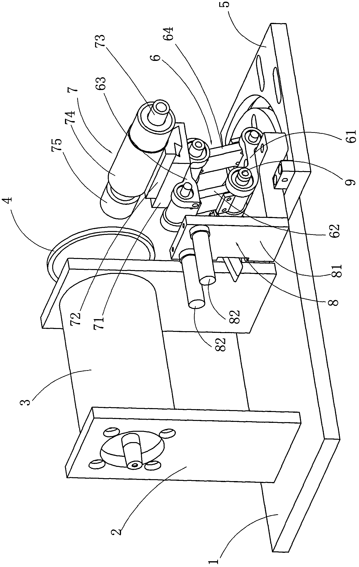
[0020] Such as figure 1 and 2 The universal knife grinder includes a motor base 1, a motor support 2 is fixed on the motor base 1, a motor 3 is fixed on the motor support 2, an output shaft of the motor 3 is connected to a grinding wheel 4, and a knife rest is fixed on the motor base 1 The base 5 and the knife rest base 5 are fixed with a support frame 6 , on which a knife rest holder 7 for fixing a knife is arranged, and a collision mechanism 8 is provided on one side of the support frame 6 .

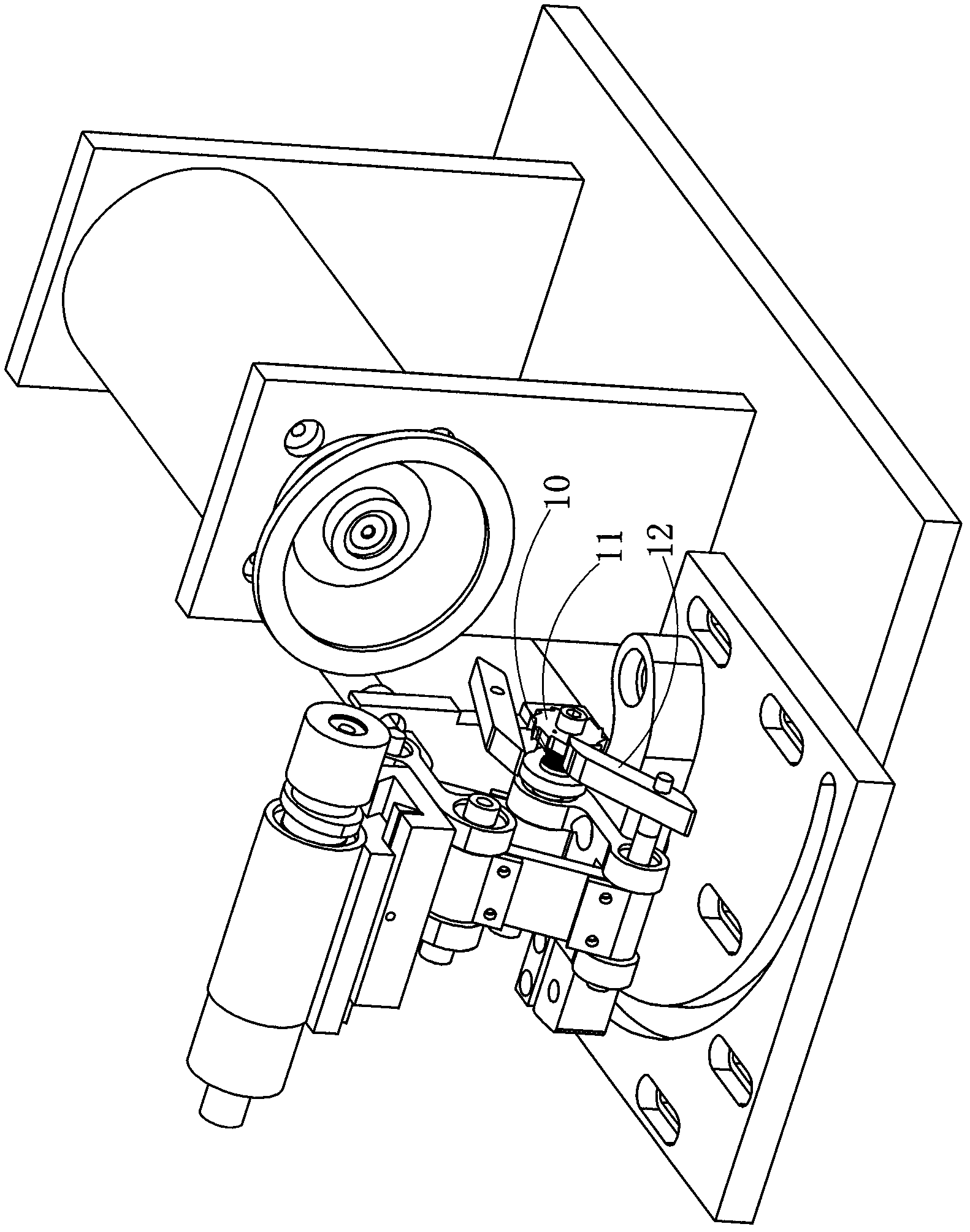
[0021] In this embodiment, the support frame 6 includes four connecting arms 61, 62, 63, 64 connected end to end to form a quadrilateral bracket, and one connecting arm 61 located at the bottom of the four connecting arms is rotatably fixed on the tool holder through a shaft. On the base 5, and the connecting parts where the four connecting arms are connected end to end are connected through the rotation of the chain rod 9; The connecting arm 62 pushes towards the torsion spring 10 o...

Embodiment 2

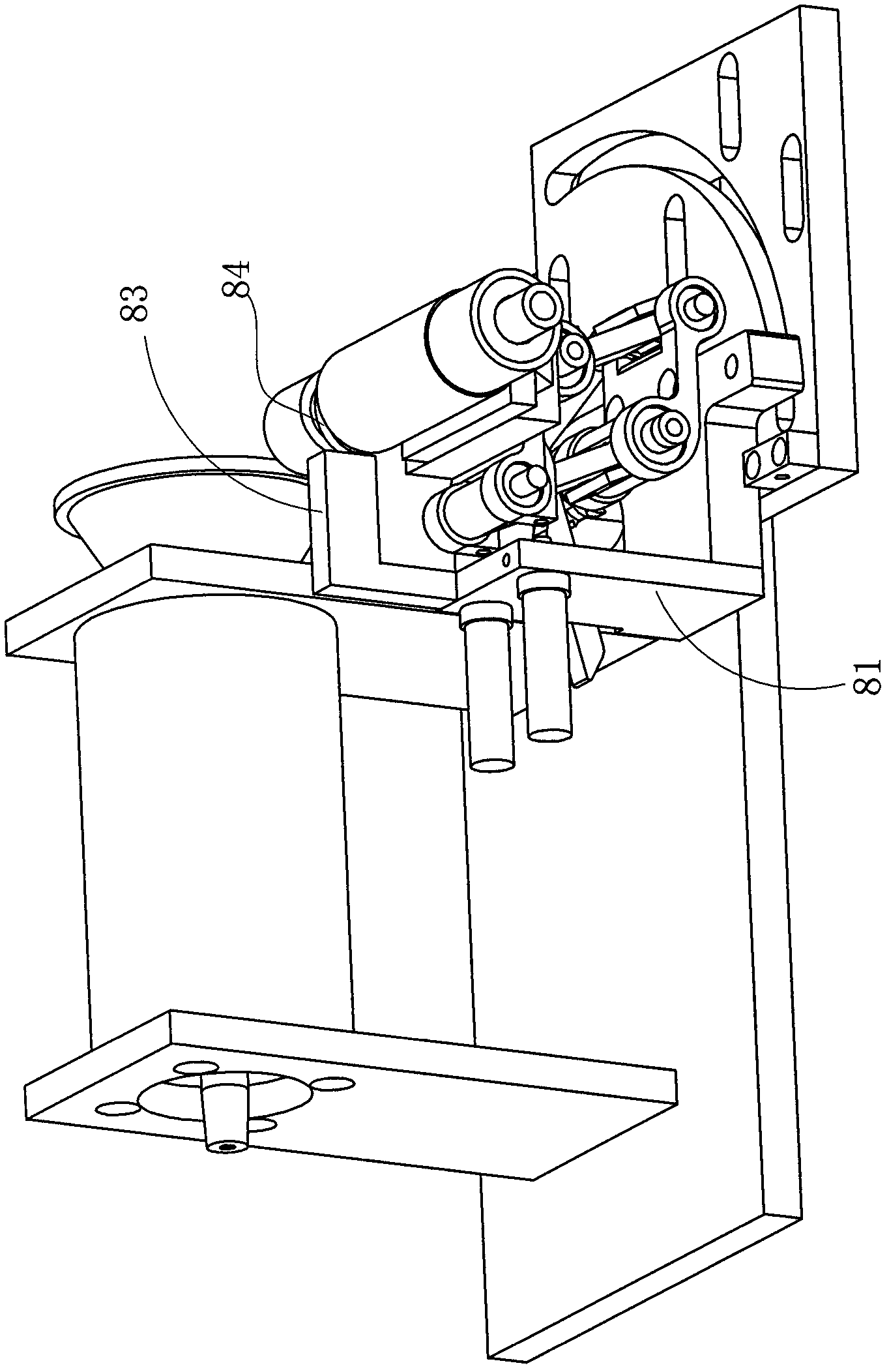
[0025] Different from the first implementation, the fixed bracket 81 is detachably provided with an L-shaped auxiliary arm 83 for grinding special-shaped knives, and the first end of the first arm in the L-shaped auxiliary arm is detachably plugged and fixed on the On the fixed bracket 81, the second end of the first support arm is connected to the first end of the second support arm, and the second end of the second support arm is connected to the cross-section of the tool rest holder 7 that is sleeved on the rotating shaft. The control sleeve 84 is a corresponding interference fit.

Embodiment 3

[0027] The difference from Embodiment 1 is that the support frame 6 includes a guide rail 65 fixed on the base of the tool holder, and a slider 66 arranged on the guide rail is moved, and the lower end of the slider is provided with a device capable of accommodating the guide rail. rail groove.


PUM


Abstract

The invention relates to a universal knife sharpener, which comprises a grinding wheel driven to rotate by a motor, a knife rest clamping seat arranged at one side opposite to the grinding wheel and used for fixing a knife, and a support frame for supporting the knife rest clamping seat, wherein the support frame is fixed on a knife rest base. The universal knife sharpener is characterized in that: the support frame can be driven to move far from or close to the grinding wheel by an external force; and in addition, the universal knife sharpener also comprises a conflicting mechanism arranged on the same side as the grinding wheel, wherein the conflicting mechanism is movably provided with a micrometer head capable of moving far from or close to the support frame. The universal knife sharpener has the advantages of low adjusting error, high precision and simple and practical structure.

Description

technical field [0001] The invention relates to a universal sharpener. Background technique [0002] Existing universal knife sharpeners generally include a motor, a grinding wheel driven by the motor, a knife holder holder for fixing the cutter, and a support frame for supporting the knife holder holder, wherein the support holder generally consists of a support screw and a support screw connected with the support screw. Composed of nuts used together, the lateral movement of the support frame is adjusted by an adjusting nut with a dial. Due to the mechanical gap between the screw and the nut, this will cause a large error when the support frame supports the tool holder holder when grinding the tool. Especially when grinding some tools with high precision requirements, this error will be particularly obvious; in addition, the tightness of the assembly between the screw and the nut will also affect the accuracy of the tool grinding; The higher the height, the greater the er...

Claims


Application Information

Patent Timeline
Patent Type & Authority Applications(China)
IPC IPC(8): B24B3/00
Inventor 邱坚峰
Owner 邱坚峰
Why Eureka
Try Eureka