
Single-screw extruder

A single-screw extruder and screw technology, which is applied in the field of extrusion equipment, can solve the problems that the gap is not easy to completely eliminate, affect the smoothness of the screw, and the feeding amount is not easy to control, etc., to achieve the convenience of continuing to move, reduce the gap, and improve the mixing. sexual effect

Active Publication Date: 2014-04-23
浙江百纳橡塑设备有限公司
View PDF8 Cites 2 Cited by
  • Summary
  • Abstract
  • Description
  • Claims
  • Application Information

AI Technical Summary

Problems solved by technology

However, the feeding amount of the extruder is not easy to control during the feeding process, and the change of the feeding amount will easily form a gap between the pellets. During the extrusion process of the pellets by the screw, if there is no special mechanical structure Processing, the change of the gap between the pellets is more reflected in the change of the gap size, the gap in the pellet is not easy to completely eliminate, after the pellets with more gaps inside enter the cavity of the injection molding machine, the pellets Some gaps in the material will form air bubbles in the wall of the injection molded part, which will affect the quality of the injection molded part
Moreover, when the single-piece push piece pushes the pellets forward, it is easy to accumulate in the groove formed between the push piece and the peripheral surface of the screw, which will affect the smoothness of the movement on the screw.

Method used


Image

  • Single-screw extruder
  • Single-screw extruder
  • Single-screw extruder

Examples


Embodiment Construction

[0023] Below by specific embodiment, in conjunction with accompanying drawing, the technical scheme of the present invention is described further in detail:

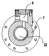
[0024] The structure of the single-screw extruder of the present invention includes a housing 7 and a screw 1. The housing 7 has a rotary cavity 12, and the screw 1 is arranged in the rotary cavity 12. The casing 7 is composed of a plurality of hollow coupling bodies 3 connected together, and a connecting flange is provided between two adjacent coupling bodies 3 to facilitate their fixed connection.

[0025] The screw 1 has a feeding part 14 and a discharging part 15, and the housing 7 is provided with a feeding port and a feeding port. The feeding part 14 on the screw 1 is located at the feeding port of the housing 7. On the screw 1 The discharge part 15 of the casing 7 is plugged into the discharge port of the casing 7, and a collection box 11 is arranged below the discharge port of the casing 7.

[0026] A main push ...


PUM


Abstract

The invention provides a single-screw extruder, which comprises a shell and a screw, wherein the screw is rotationally arranged in a rotating cavity of the shell; a main push plate is arranged on the peripheral surface of the screw, and the main push plate is spirally extended on the peripheral surface of the screw; the shell is provided with a feeding hole and a discharge hole; the screw is provided with a feeding part and a discharge part, the feeding part of the screw is positioned at the feeding hole of the shell, and the discharge part of the screw is positioned in the discharge hole of the shell; a spiral structure extended spirally is arranged on the peripheral surface of the feeding part of the screw, and the pitch of the spiral structure is different from the pitch of the feeding part of the screw; and the spiral structure is crossed with the main push plate once at least, so that a sharp angular shearing structure is formed at the crossed part of the spiral structure and the main push plate. Through the extruder, the gaps of the extruded granules are small, the quality of subsequent injection molding pieces can be ensured, and the advancing smoothness of the granules on the screw is good.

Description

technical field [0001] The invention relates to an extrusion equipment for mixing and extruding granular raw materials and outputting them, more specifically, the invention relates to a single-screw extruder. Background technique [0002] The extruder is used to fully mix and extrude a variety of granular raw materials and then output them. It is mainly used in the field of plastic or rubber manufacturing machinery. A single-screw extruder is disclosed in the Chinese invention patent (patent number: 200910003544.2), the structure of which includes a housing with at least one hole and a front wall surrounding the hole. A recess is formed in the front wall concentrically with the hole. A worm is disposed in the bore, the worm comprising a cylindrical bearing portion outwardly through the recess. A packing seals against the recess and the support portion, the packing abutting against a counter support in the direction of the hole. A sliding bearing is arranged on the bearing...

Claims


Application Information

Patent Timeline
Patent Type & Authority Patents(China)
IPC IPC(8): B29C47/38B29C47/60B29C48/395B29C48/615
CPCB29C47/6018B29C47/385B29C47/6075B29C47/6081B29C47/6025B29C48/397B29C48/53B29C48/535B29C48/62B29C48/615
Inventor 项军伟
Owner 浙江百纳橡塑设备有限公司
Learn More